Self-heat-insulation flexible interlayer air duct for tunneling roadway or vertical shaft

A technology for shafts and tunnels, which is applied in the improvement field of self-insulating flexible interlayer air ducts, which can solve the problems of inability to guarantee the comfort of the deep environment, the deviation of the cold air temperature from the design temperature, and uneconomical conditions, so as to achieve the best thermal insulation effect and improve work efficiency. The effect of efficiency and simple structure

Active Publication Date: 2019-05-14
CHINA UNIV OF MINING & TECH
View PDF7 Cites 1 Cited by
  • Summary
  • Abstract
  • Description
  • Claims
  • Application Information

AI Technical Summary

Problems solved by technology

But this method is not economical. The inside of the air duct conveys low-temperature air, while the outer surface of the air duct is in a high-temperature environment, which makes the internal and external air flow have a large temperature difference. The heat is transferred from the high-temperature end to the low-temperature section to heat the cold air, resulting in actual The deviation between the temperature of the cold air reaching the working surface and the design temperature cannot guarantee the comfort of the deep environment

Method used


Image

  • Self-heat-insulation flexible interlayer air duct for tunneling roadway or vertical shaft
  • Self-heat-insulation flexible interlayer air duct for tunneling roadway or vertical shaft
  • Self-heat-insulation flexible interlayer air duct for tunneling roadway or vertical shaft

Examples


Embodiment Construction

[0026] The technical solutions in the embodiments of the present invention will be clearly and completely described below in conjunction with the drawings in the embodiments of the present invention.

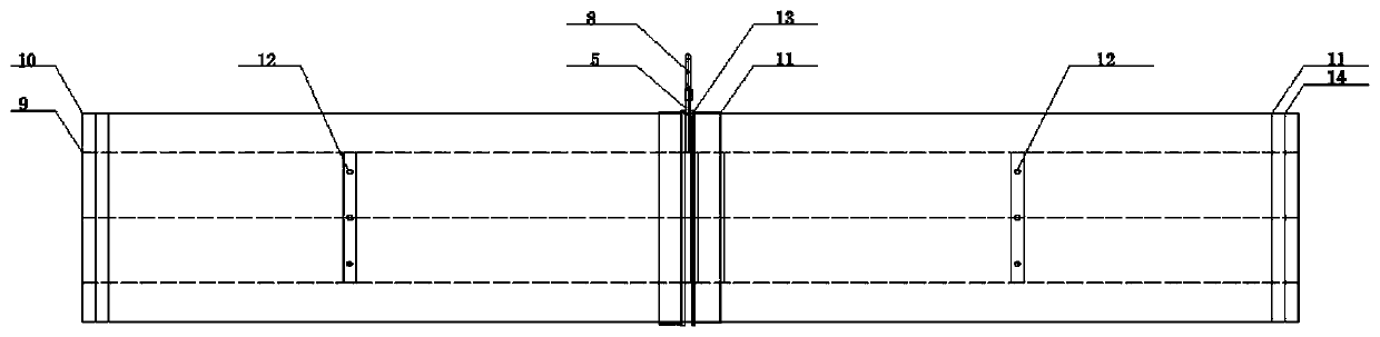
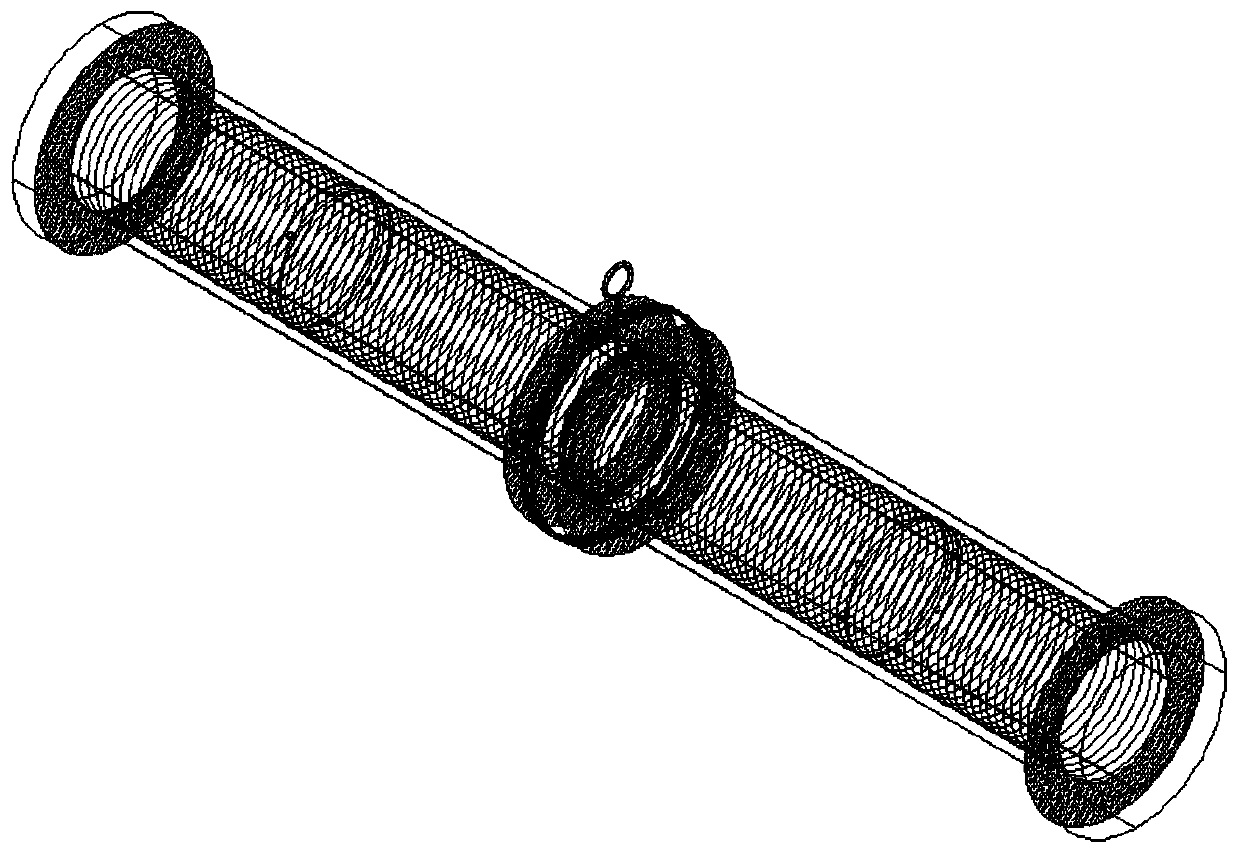
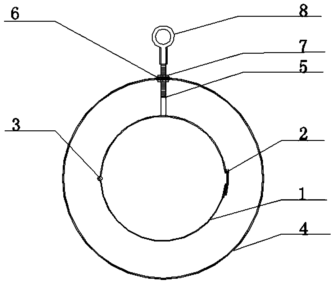
[0027] reference Figure 1-5 , The present invention provides the following technical solutions: a self-insulating flexible interlayer air duct for roadway or shaft excavation, including its main structure and connecting parts. The main structure consists of an inner air duct 9, an outer air duct 10 and an annular interlayer 11 The two ends of the air duct are overlocked with fixed iron rings 14, and the middle of the inner air duct is provided with eight vent holes 12 evenly arranged in a circumferential direction, which is convenient for inflating the interlayer space. The edges of the vent holes 12 are clamped by metal sheets. Prevent the hair dryer cloth from tearing. The annular inter-cloth 11 includes a head-end inter-cloth and a tail-end inter-cloth. The inner ring of the i...


PUM


Abstract

The invention discloses a self-heat-insulation flexible interlayer air duct for tunneling a roadway or vertical shaft. The self-heat-insulation flexible interlayer air duct comprises an air duct mainbody structure and a matched connecting assembly. The air duct main body structure comprises inner-layer air duct cloth, outer-layer air duct cloth and annular space cloth, and the connecting assemblycomprises hoops, a threaded rod and an outer rib ring. The two ends of an inner-layer air duct are fixedly connected through the hoops, outer-layer air ducts are arranged on the two sides of the outer rib ring in a sleeving mode and fixed through the hoops, an annular closed space is formed by the cloth between the head end and the tail end and the cloth of the inner-layer air duct and the outer-layer air duct, the optimal interlayer thickness of the air duct is 30 mm through a numerical calculation method, the thermal resistance value is maximum when the interlayer thickness is obtained, andthe heat preservation effect of the air duct is best. The interlayer air duct reduces heat exchange between cold air in the air duct and the external environment, so that the temperature of the coldair fed into the working surface is close to the design standard; and the design size of the interlayer air duct is standardized, so that the heat preservation effect of the interlayer air duct is optimal under corresponding design conditions. The connecting assembly is simple in structure and flexible to disassemble, installation time can be saved in actual operation, and efficiency is improved.

Description

Technical field [0001] The invention relates to an improved technology for a self-insulating flexible interlayer air duct used for roadway or shaft excavation, in particular to a sandwich air duct structure with heat preservation and energy saving functions. Background technique [0002] With continuous breakthroughs in the mining depth of mines, more and more attention has been paid to the problem of thermal hazards in mines. The harsh temperature and humidity environment in deep thermal mines will not only endanger the physical and mental health of underground workers, reduce labor production efficiency, and even make safe production in the mine. Brings a huge threat. In recent years, various measures have been adopted for mine cooling at home and abroad. The most common way is to use refrigeration equipment (air conditioners) to send cold air into a single-layer air duct through a local fan and then transport it to the working surface to play a role in cooling the mine. Howev...

Claims


Application Information

Patent Timeline
Patent Type & Authority Applications(China)
IPC IPC(8): E21F1/04E21F1/06E21F17/02
Inventor 王义江谢宗刚袁兆宽郑通达杨金宏付万贵周国庆
Owner CHINA UNIV OF MINING & TECH
Why Eureka
Try Eureka