Multi-serial-port parallel communication transformer
A technology of transformers and multi-serial ports, used in inductors, transformer/inductor cooling, instruments, etc., can solve the problems of narrow use frequency, transformer damage, small dynamic range, etc., to reduce energy consumption, easy installation, The effect of shortening the trace distance
- Summary
- Abstract
- Description
- Claims
- Application Information
AI Technical Summary
Problems solved by technology
Method used
Image
Examples
Embodiment 1
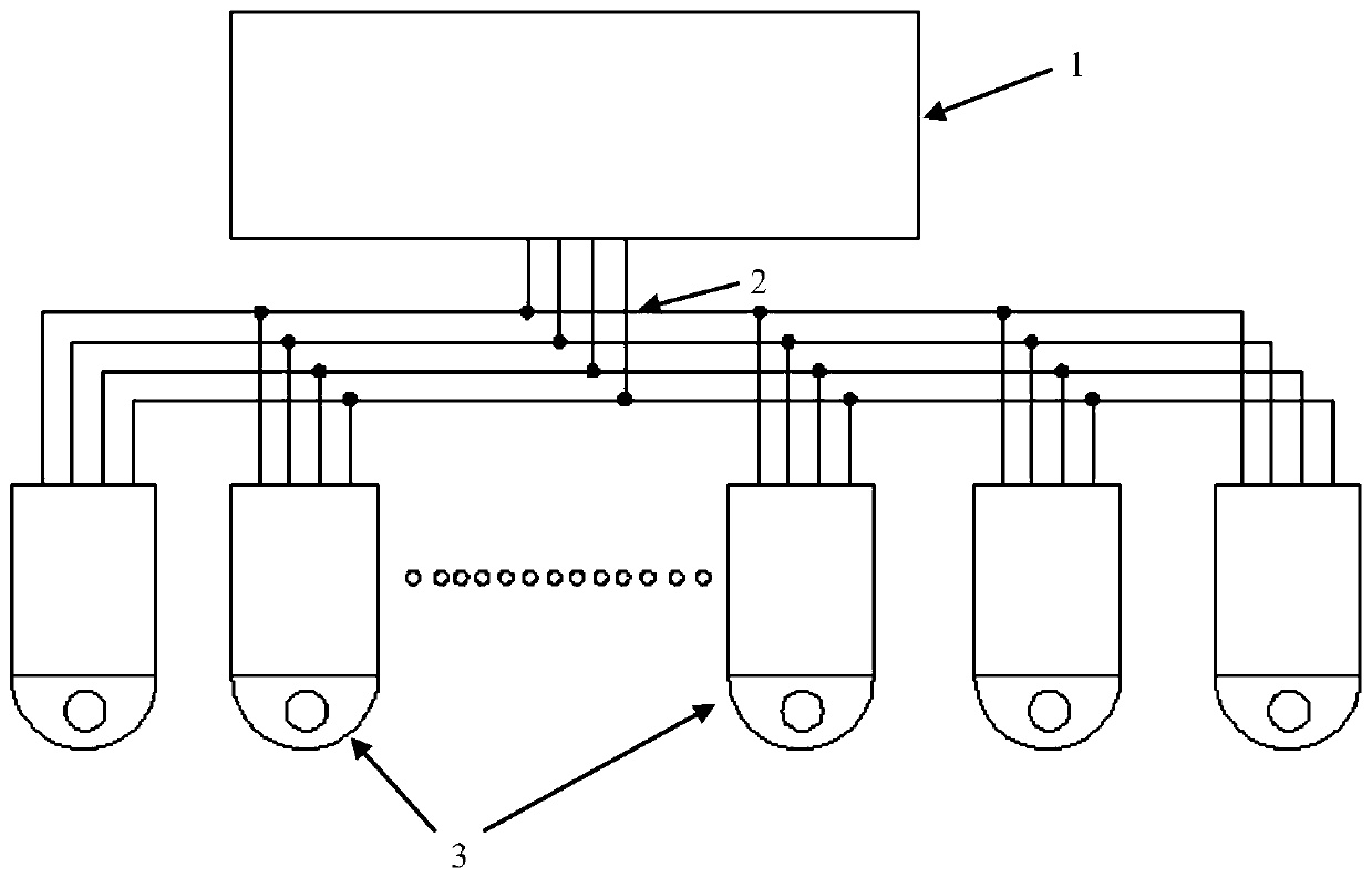
[0026] Such as figure 1 As shown, the present invention is a multi-serial port parallel communication transformer, including a device communication platform 1 and several transformers 3 connected in parallel with the device communication platform 1 through the M-BUS bus 2; wherein, the device communication platform 1 and each transformer 3 communicate with each other through an independent communication protocol, and the communication between multiple transformers 3 adopts a polling method to transmit data. The transformer 3 is a digital transformer 3 .
Embodiment 2
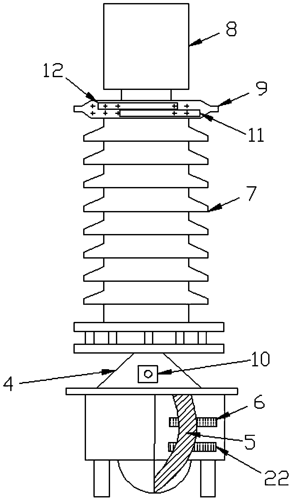
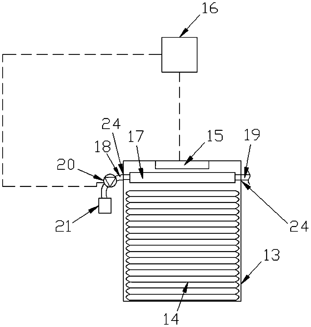
[0028] The difference from Embodiment 1 is that, as Figure 2 to Figure 8 shown (for ease of illustration, figure 2 The cooling medium inlet pipe, cooling medium outlet pipe, driving pump and storage tank are not shown; image 3 heat sink not shown), the transformer 3 is an oil-immersed current transformer 3, the oil-immersed current transformer 3 includes an oil tank 4, the upper end of the oil tank 4 is fixedly connected with the lower end of the porcelain sleeve 7, and the upper end of the porcelain sleeve 7 It is fixedly connected with the expander 8. The expander 8 includes a casing 13 and a corrugated expander body 14 arranged in the casing 13. The middle part of the corrugated expander body 14 is fixedly arranged on the casing 13. Insulating oil, the corrugated expander body 14 and its outer shell 13 are also provided with several vertical heat dissipation pipes 33, each heat dissipation pipe 33 is provided with a piston rod 26, and one end of the piston rod 26 is fix...
Embodiment 3
[0030] The difference with Embodiment 2 is that, as Figure 9 As shown, the outer housing 13 of the corrugated expander body 14 is also provided with several vertical cooling grooves 25. The housing 13 is vertically arranged, and the cooling grooves 25 are vertically arranged. The groove bottom walls of all the cooling grooves 25 Both are located at the bottom of the corrugated expander body 14 , the bottom end of the piston rod 26 is fixed with a rubber piston 27 , and the top end of the piston rod 26 is fixedly connected to the inner top wall of the housing 13 .
PUM
 Abstract
Description
Claims
Application Information
 - R&D
- Intellectual Property
- Life Sciences
- Materials
- Tech Scout
- Unparalleled Data Quality
- Higher Quality Content
- 60% Fewer Hallucinations
Browse by: Latest US Patents, China's latest patents, Technical Efficacy Thesaurus, Application Domain, Technology Topic, Popular Technical Reports.
© 2025 PatSnap. All rights reserved.Legal|Privacy policy|Modern Slavery Act Transparency Statement|Sitemap|About US| Contact US: help@patsnap.com


