
Evaporation concentration system

An evaporative concentration system, cooling water system technology, applied in the direction of evaporation, evaporator accessories, chemical instruments and methods, etc., can solve the problems of untimely discharge, damage to pipes and valves, insufficient utilization of condensed water, etc. Increase the cooling effect, prevent the effect of liquid shock and air entrapment

Pending Publication Date: 2019-05-10
SHAANXI SHANHUA COAL CHEM IND GRP
View PDF6 Cites 1 Cited by
  • Summary
  • Abstract
  • Description
  • Claims
  • Application Information

AI Technical Summary

Problems solved by technology

Among them, the condensed water output of the heater is affected by many aspects such as the amount of water in the steam, steam saturation, steam temperature, and vacuum degree of the evaporation system. Therefore, the drainage rate of steam traps and other equipment needs to be adjusted according to the actual situation. Excessive condensed water on the steam trap will cause liquid shock in the pipeline, or discharge too fast to cause air leakage. Both liquid impact and air leakage will cause vibration of pipelines and valves, resulting in damage to pipelines and valves, water leakage, and air leakage.
[0004] At the same time, in the process of evaporation and concentration, the water from the product and the condensed water from the heater cannot be fully utilized, resulting in waste of water resources

Method used


Image

  • Evaporation concentration system
  • Evaporation concentration system
  • Evaporation concentration system

Examples


Embodiment 1

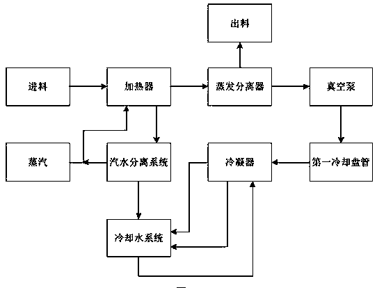
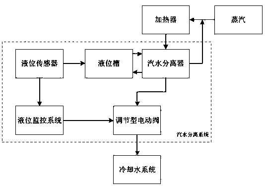
[0032] Refer to attached Figure 1-4 As shown, an evaporative concentration system includes a heater and an evaporative separator, the outlet of the heater is connected to the feed port of the evaporative separator, and a steam-water separation system is connected to the heater; the steam-water separation system Including steam-water separator, liquid level tank, liquid level sensor, liquid level monitoring system and regulating electric valve, steam-water separator is connected with liquid level tank, liquid level sensor is set inside liquid level tank, regulating electric valve and steam-water separator The drain port is connected, the liquid level monitoring system is connected with the liquid level sensor, and the liquid level monitoring system is connected with the regulating electric valve; the liquid level monitoring system controls the opening degree of the regulating electric valve according to the liquid level sensor.

[0033] When the evaporative concentration syste...

Embodiment 2

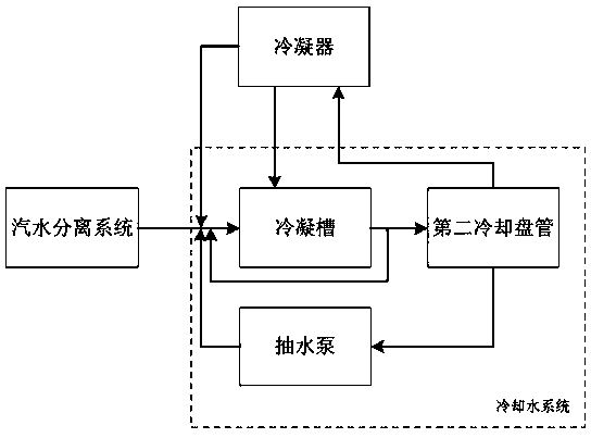
[0040] Please refer to Figure 1-4 As shown, the difference between this embodiment and Embodiment 1 is that this embodiment optimizes the design of the cooling water system and better recovers the water vapor generated by evaporation and separation.

[0041] In this embodiment, a first cooling curved plate is also included, and the first cooling curved plate is arranged between the vacuum pump and the condenser. The first cooling curved plate accelerates the cooling and liquefaction of water vapor to increase the liquefaction speed. If the vacuum book directly extracts water vapor into the air, water resources will be wasted, and the surrounding air humidity will be increased at the same time, and there will be a hidden danger of rusting of the equipment. Using a condenser to treat the water vapor generated by the evaporative separator may have insufficient liquefaction speed, which will lead to blockage of the pipe, resulting in an increase in the pressure in the pipe, and ...

Embodiment 3

[0045] Please refer to Figure 1-4 As shown, the difference between this embodiment and Embodiment 2 is that this embodiment optimizes the drainage structure of the steam-water separator to prevent special accidents.

[0046] In this embodiment, a first shut-off valve and a second shut-off valve are also included. The first shut-off valve is arranged between the drain port of the steam-water separator and the adjustable electric valve, and the second shut-off valve is arranged between the steam-water separator and the cooling water outlet. between systems. Two cut-off valves are set to prevent the regulating electric valve from malfunctioning. The first cut-off valve can be used to close the pipeline, and the second cut-off valve can be used to open the second pipeline to ensure drainage. When the first stop valve is in the open state, the second stop valve is in the closed state; when the first stop valve is in the closed state, the second stop valve is in the open state. T...


PUM


Abstract

The invention provides an evaporation concentration system. The evaporation concentration system is characterized in that a discharge outlet of a heater is connected with a feed inlet of an evaporation separator, and a steam-water separation system is connected with the heater; a steam-water separator is connected with a liquid level tank, a liquid level sensor is arranged inside the liquid leveltank, a regulation type electric valve is connected with a drain opening of the steam-water separator, and a liquid level monitoring system is connected with the liquid level sensor and is connected with the regulation type electric valve; the opening degree of the regulation type electric valve can be controlled by the liquid level monitoring system according to the liquid level sensor. Accordingto the scheme, the evaporation concentration system has the advantages that the liquid level tank is communicated with the steam-water separator, the internal liquid level of the liquid level tank can be measured by the liquid level sensor, and accordingly the height of the liquid level of the steam-water separator can be monitored; the opening degree of the regulation type electric valve can beregulated by the liquid level monitoring system according to data of the liquid level sensor, so that the drain speed of the steam-water separator can be controlled, the liquid level of the steam-water separator can be guaranteed against being excessively high or excessively low, and liquid impact and gas movement phenomena can be prevented.

Description

technical field [0001] The invention relates to the field of evaporation concentration, in particular to an evaporation concentration system. Background technique [0002] In the food industry and chemical industry, many products need to be concentrated. As a process in the production process, the water in the product is mainly converted into water vapor and evaporated from the product solution to increase the product concentration. For example, dairy products in food, urea in chemical industry, etc. need to be evaporated and concentrated for the next step. [0003] In the concentration, the method of evaporation and concentration is often used for concentration, and the use of hot steam as the heat source is the most widely used. In the process of heating with hot steam, a large amount of water needs to be discharged. Generally, devices such as steam traps are used to discharge the condensed water of the heater. Among them, the condensed water output of the heater is affe...

Claims


Application Information

Patent Timeline
IPC IPC(8): B01D1/00B01D1/30
Inventor 仵杨波边利利封建利张进华海成立白延军
Owner SHAANXI SHANHUA COAL CHEM IND GRP
Learn More