
Method for suppressing combustion pressure pulsation by high-frequency excitation discharge center plasma

A plasma and pressure pulsation technology, applied in the direction of plasma, electrical components, etc., can solve the problems of large actuation time delay, insufficient actuation frequency, mechanical loss, etc., to achieve improved heat release stability, stable flame shape, pressure Pulsation reduction effect

Active Publication Date: 2019-05-07
HARBIN INST OF TECH
View PDF6 Cites 3 Cited by
  • Summary
  • Abstract
  • Description
  • Claims
  • Application Information

AI Technical Summary

Problems solved by technology

[0004] The present invention aims to solve the technical problems of insufficient actuation frequency, large actuation time delay, and mechanical loss in the existing method for suppressing combustion pressure pulsation, and provides a method for suppressing combustion pressure pulsation by exciting discharge center plasma at high frequency

Method used


Image

  • Method for suppressing combustion pressure pulsation by high-frequency excitation discharge center plasma
  • Method for suppressing combustion pressure pulsation by high-frequency excitation discharge center plasma
  • Method for suppressing combustion pressure pulsation by high-frequency excitation discharge center plasma

Examples


specific Embodiment approach 1

[0014] Specific implementation mode 1: This implementation mode is a method for suppressing combustion pressure pulsation by high-frequency exciting discharge center plasma, which is specifically carried out according to the following steps:

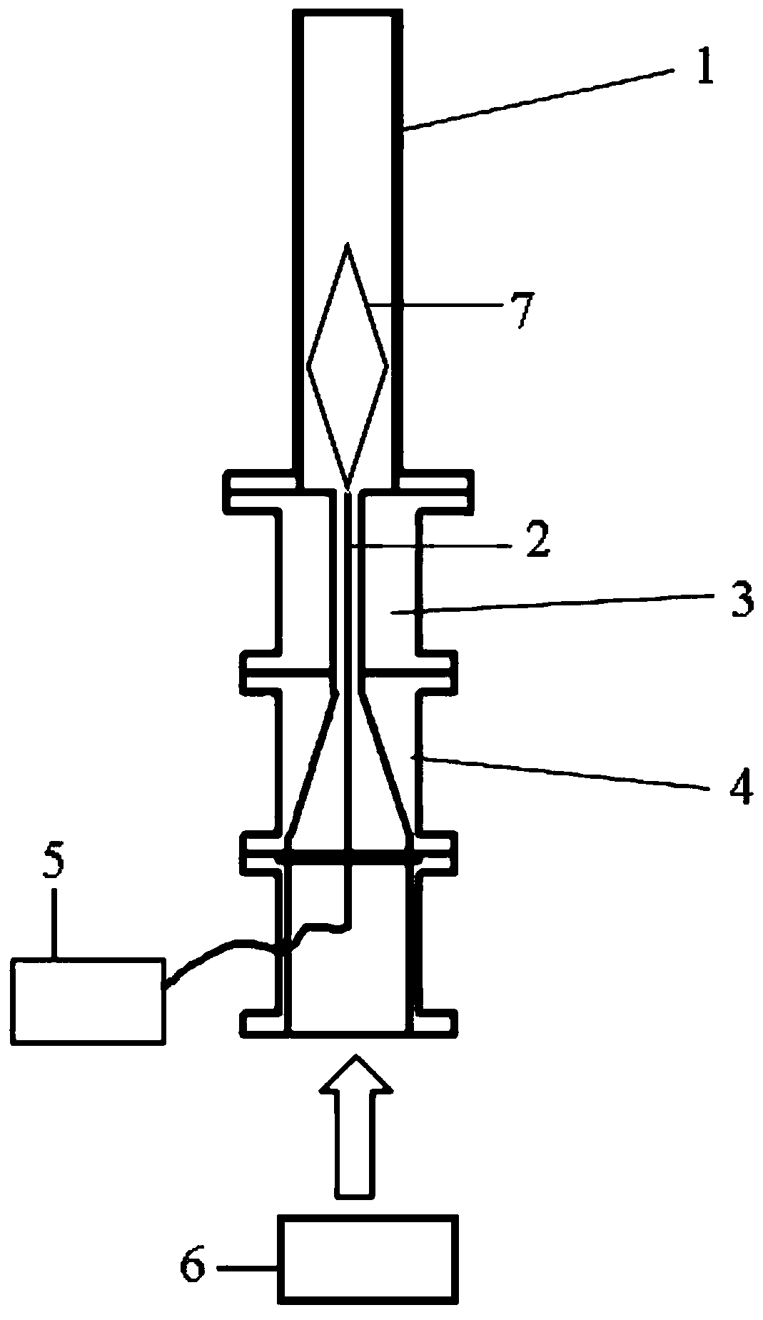
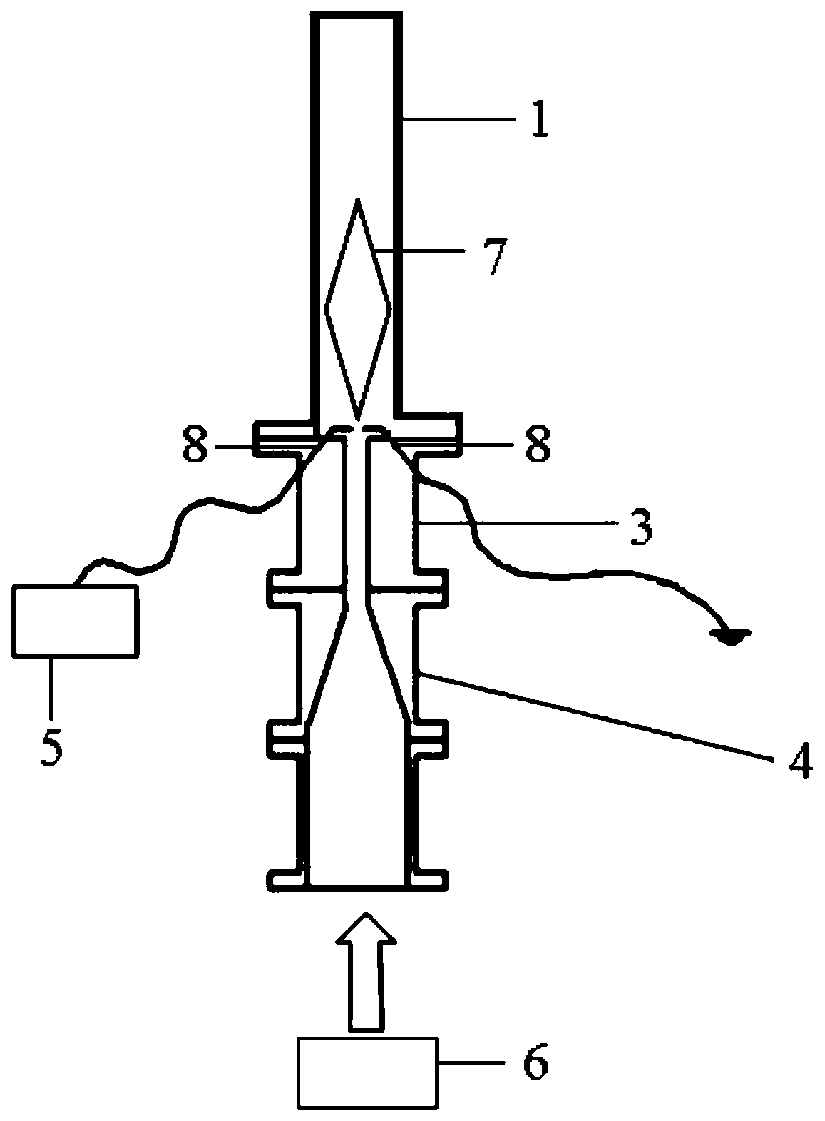
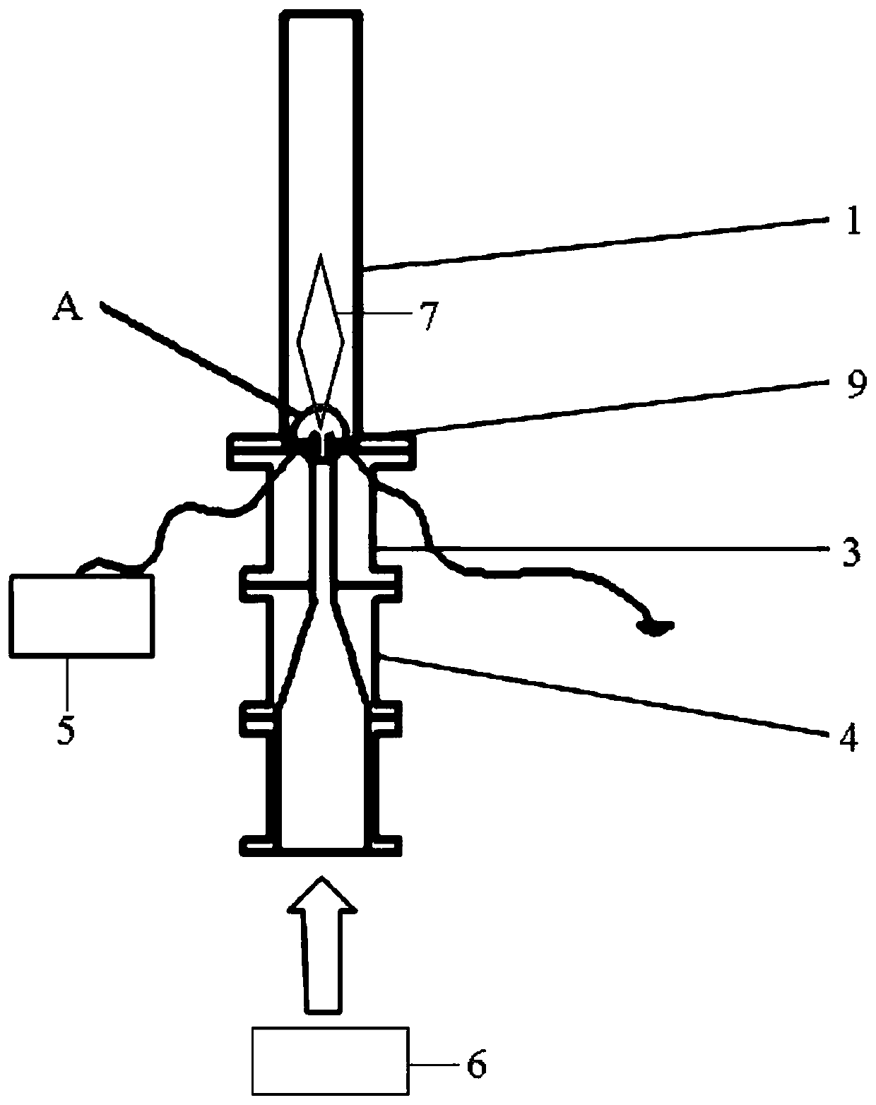
[0015] Place the metal electrode at the center of the entrance of the combustion chamber, connect the metal electrode to the output end of the power supply outside the combustion chamber, feed combustible premixed gas into the combustion chamber and ignite it, when thermoacoustic oscillation occurs in the combustion chamber accompanied by a certain degree of When the pressure fluctuates, start the power supply outside the combustion chamber, so that the metal electrode generates plasma discharge inside the combustion chamber, and acts on the root of the thermoacoustic oscillation flame inside the combustion chamber, and adjusts the discharge frequency of the plasma to an integer multiple of the flame pulsation frequency (1kHz-50kHz), whil...

specific Embodiment approach 2

[0016] Embodiment 2: The difference between this embodiment and Embodiment 1 is that the metal electrode is a metal suspension single electrode, and the lower end of the metal suspension single electrode is connected to the output end of the power supply outside the combustion chamber, with infinity as the ground electrode. Others are the same as the first embodiment.

specific Embodiment approach 3

[0017] Embodiment 3: The difference between this embodiment and Embodiment 1 or 2 is that the metal electrode is a metal double electrode, and a pair of metal double electrodes are installed near the root of the flame in an opposite arrangement. Each electrode is connected to the output end of the power supply outside the combustion chamber and the ground wire respectively. Others are the same as those in Embodiment 1 or 2.


PUM


Abstract

A method for suppressing combustion pressure pulsation by a high-frequency excitation discharge center plasma relates to a method for suppressing pressure pulsation in a thermoacoustic oscillation phenomenon. The method uses plasma as a dynamic and active way to regulate the pressure pulsation state of a combustion chamber which occurs during combustion under a certain working condition. The plasma is generated at the flame root of the combustion chamber, so that the flame is dynamically affected by the plasma and is less affected by the disturbance of an air flow. Thus, the heat release stability is correspondingly improved, and the phase and frequency of the flame heat release are adjusted, so that the degree of amplification of the pulsating energy of the combustion chamber is reduced,and the condition of the thermoacoustic oscillation is destroyed, thereby realizing the reduction or even disappearance of the pressure pulsation in the combustion chamber.

Description

technical field [0001] The invention relates to a method of suppressing combustion pressure pulsation. Background technique [0002] Under certain operating conditions, some unexpected instability will occur inside the combustion chamber, that is, when the relative phase between the sound pressure and the unsteady heat release is between +90° and -90°, the combustion system Energy will be amplified. If this amplified energy is greater than the energy dissipated at the chamber boundary, the average net energy accumulated over one oscillation cycle of the chamber increases and eventually leads to the occurrence of thermoacoustic oscillation phenomena. On the one hand, this instability phenomenon can promote the mixing of fuel-air, enhance the mixing effect, and facilitate the combustion; but on the other hand, it will cause additional pressure, high-amplitude oscillation of the flow field and flame, heat load As the height increases, the generation of pollutants will intensi...

Claims


Application Information

Patent Timeline
Patent Type & Authority Applications(China)
IPC IPC(8): H05H1/26
Inventor 唐井峰郭宸杨广薇朱悉明翟明于达仁
Owner HARBIN INST OF TECH
Learn More