


Quick Research
Generate reliable direction feasibility study reports for your R&D in just a few steps.

Technical Q&A
Discover and master advanced knowledge NOW. Basics, ideas, possibilities, all at once.

Find Solutions
As an expert in R&D theories, this can generate solutions to your technical problems instantly.

Evaluate Feasibility
Analyze your overall solution with one click, know your potential R&D risks in advance.

Monitor Landscape
Get weekly tech updates, stay abreast of the latest tech innovations and key insights.
Releasing mechanism of engine flow baffle
A technology of releasing mechanism and baffle, applied in the direction of machine/engine, rocket engine device, mechanical equipment, etc., can solve the problems of flight failure, collision with arrow body, escape failure, etc., to achieve accurate and rapid control effect, stable and reliable connection , lock and release process is simple and easy
- Summary
- Abstract
- Description
- Claims
- Application Information
AI Technical Summary
Problems solved by technology
Method used
Image

Examples
Embodiment Construction
[0016] The present invention will be described in detail below with reference to the accompanying drawings and examples.
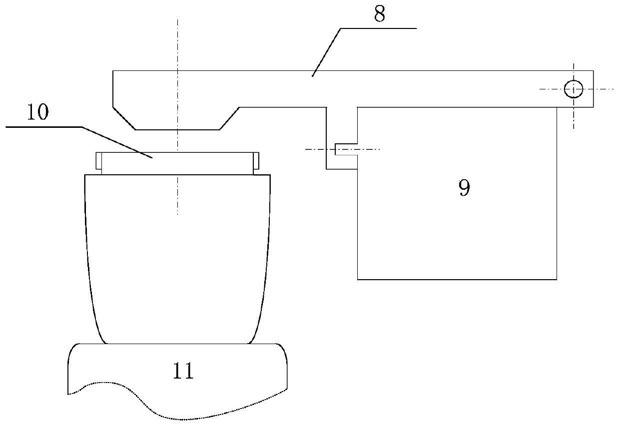
[0017] Such as figure 1 As shown, it is a schematic diagram of the installation position of the engine variable thrust baffle and the release mechanism. The rear part of the baffle 8 is installed by a rotating shaft and can be turned over; the front end is located at the nozzle of the nozzle 10 of the engine 11; the release mechanism 9 of the present invention is installed The middle part of the baffle 8 can realize locking and release of the baffle 8 .
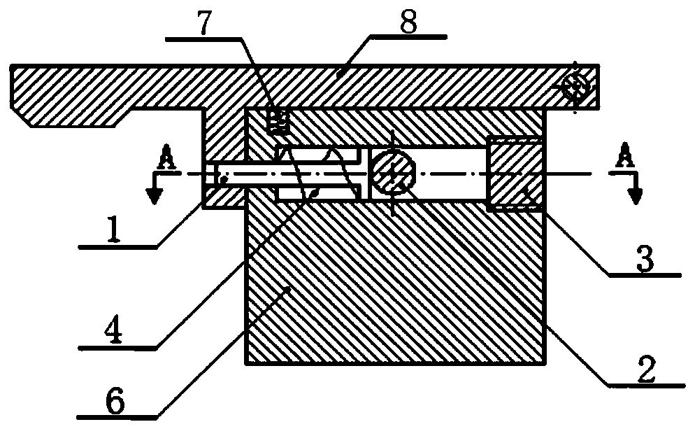
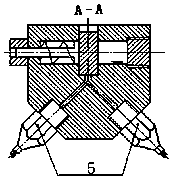
[0018] As shown in 2(a) and 2(b), the release mechanism 9 of the present invention includes a locking pin 1, a release pin 2, a screw 3, a pin spring 4, an electric squib 5, a support 6 and a release spring 7.
[0019] The support 6 is installed close to the lower surface of the baffle 8, and there are two inner passages perpendicular to each other inside the support 6: the first passage in the shape of ...
PUM
 Abstract
Description
Claims
Application Information
 - R&D Engineer
- R&D Manager
- IP Professional
- Industry Leading Data Capabilities
- Powerful AI technology
- Patent DNA Extraction
Browse by: Latest US Patents, China's latest patents, Technical Efficacy Thesaurus, Application Domain, Technology Topic, Popular Technical Reports.
© 2024 PatSnap. All rights reserved.Legal|Privacy policy|Modern Slavery Act Transparency Statement|Sitemap|About US| Contact US: help@patsnap.com