Ophthalmic lenses for treating myopia
A technology of ophthalmic lenses and glasses, applied in the direction of glasses/protective glasses, glasses/goggles, applications, etc.
- Summary
- Abstract
- Description
- Claims
- Application Information
AI Technical Summary
Problems solved by technology
Method used
Image

Examples
Embodiment
[0106] Initial studies / comparative examples
[0107] In previous studies, proof-of-concept glasses using diffusing color filters attached to the lens surface were found to slow axial length growth in subjects, but many puzzles remained. The color filter used was a commercially available Bangerter Blackout Foil ("BOF"). These are diffusers made of thin flexible electrostatic vinyl film trimmed to match the lens shape and adhered to the right lens. The "foil" used was "BOF-0.8Acuity of 20 / 25" which, as the name suggests, is nominally optimal for corrected visual acuity down to 20 / 25. In practice, however, the acuity of subjects that can be best corrected in the range 20 / 15-20 / 20, field tested with BOF-0.8 filters in the range 20 / 30-20 / 40 . Subjects in this study wore diffusers unilaterally on a single eye because of the greatly reduced acuity it produced and were concerned about the tolerability and safety of wearing glasses that would reduce binocular acuity to 20 / 30-40....
Embodiment 2
[0118] Example 2: Prototype II
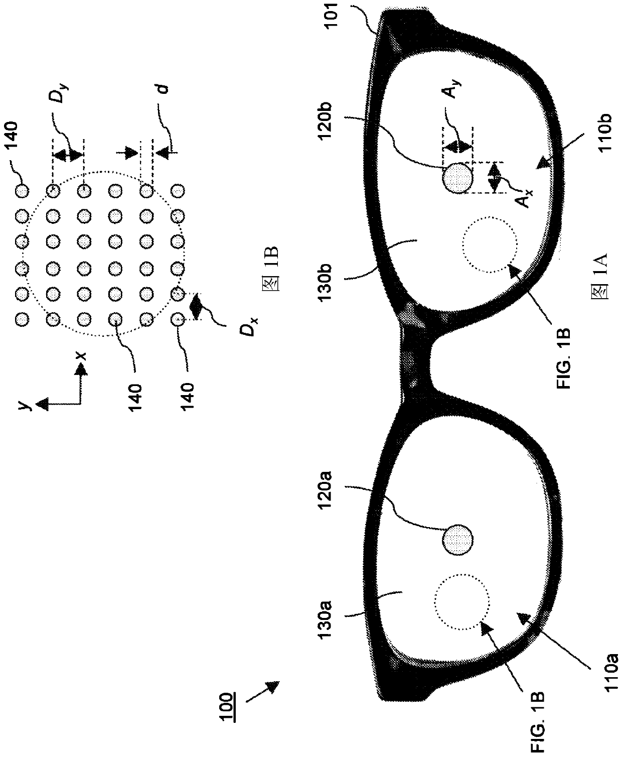
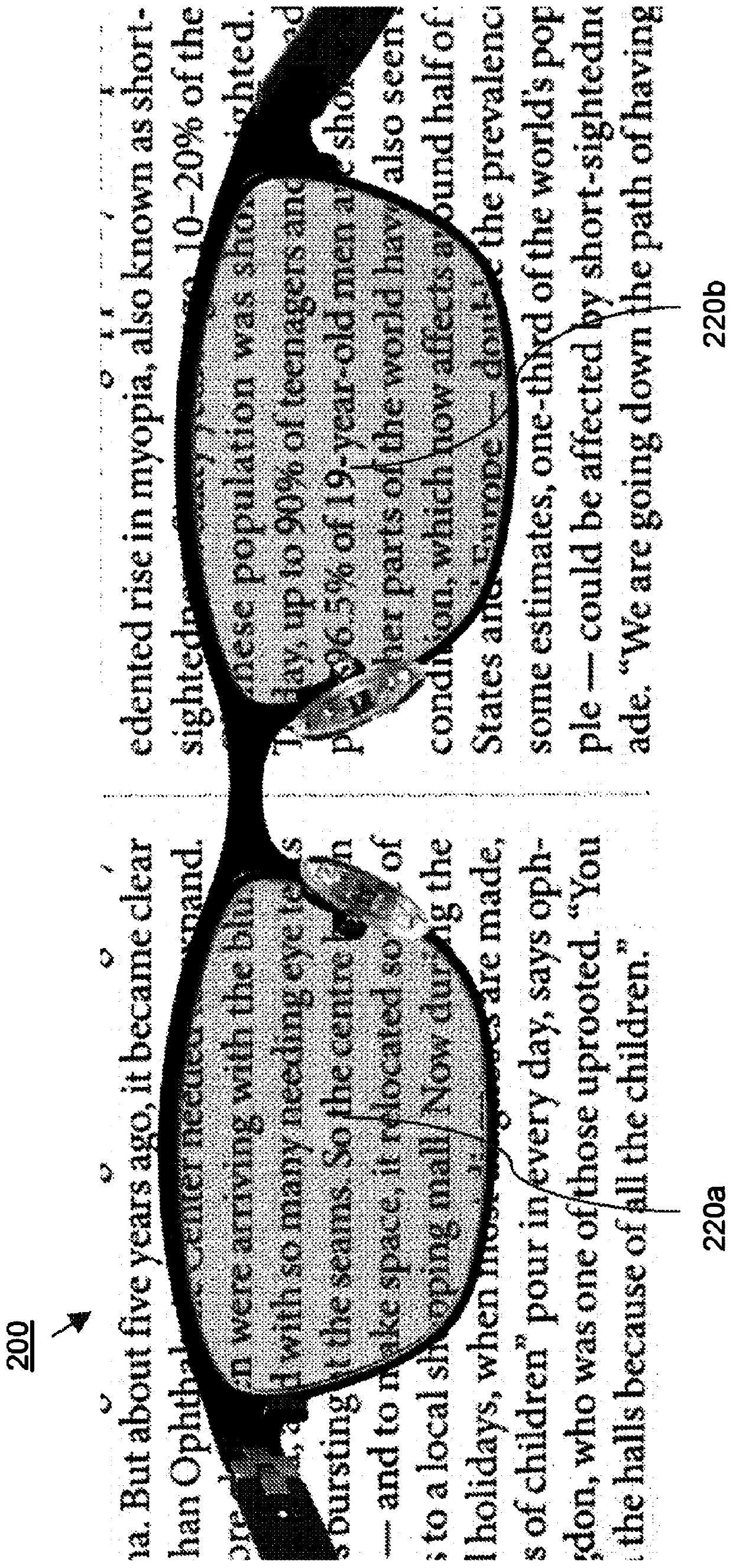
[0119] The goal of Prototype II was to produce a lens that would allow best corrected visual acuity measured in the 20 / 15 to 20 / 20 range, but be equal to or better than the BOF-0.8 filter. To this end, Prototype II lenses were produced by modifying the Prototype I dot pattern to include a small central clear area. The dots are formed on a square grid pattern with a pitch of 0.55 mm. The clear aperture is formed in a circular shape with a diameter of 3.8 mm. exist Figure 9 A photograph of the Prototype II lens is shown in .
[0120] When the glasses are worn, the clear area is positioned to match the pupil, allowing the wearer to see through the clear area when looking straight ahead. Subjects with a best correction of 20 / 15-20 / 20 tested 20 / 15-20 / 20 when wearing Prototype II and looking through the transparent area to read the eye chart.
[0121] The clear zones of Prototype II and Prototype I were tested by recruiting a small number of ...
Embodiment 3
[0122] Example 3: Prototype III
[0123] Additional improvements are explored to maximize both tolerability and efficacy. It is generally believed that the larger the transparent area, the more tolerant the prototype, but it was also hypothesized that increased peripheral contrast reduction might improve efficiency. Therefore, these two variants were tested, which resulted in another prototype: Prototype III. Like Prototypes I and II, Prototype III has no spectral light filtering. The dot pattern of Prototype III was modified to include a larger clear aperture than Prototype II and greater contrast reduction outside of the clear region. Specifically, the clear aperture was enlarged to 5.0mm diameter, and the square grid pitch was reduced to 0.365mm. Dot size remains the same as Prototype II. exist Figure 10 A photograph of the Prototype III lens is shown in .
[0124]The design goal was to develop a prototype that achieves good vision that is enjoyable and comfortable...
PUM
| Property | Measurement | Unit |
|---|---|---|
| Biggest size | aaaaa | aaaaa |
| Maximum horizontal size | aaaaa | aaaaa |
| Maximum horizontal size | aaaaa | aaaaa |
Abstract
Description
Claims
Application Information
 - Generate Ideas
- Intellectual Property
- Life Sciences
- Materials
- Tech Scout
- Unparalleled Data Quality
- Higher Quality Content
- 60% Fewer Hallucinations
Browse by: Latest US Patents, China's latest patents, Technical Efficacy Thesaurus, Application Domain, Technology Topic, Popular Technical Reports.
© 2025 PatSnap. All rights reserved.Legal|Privacy policy|Modern Slavery Act Transparency Statement|Sitemap|About US| Contact US: help@patsnap.com