
Blast lamp suitable for VAD deposition

A blowtorch and lamp body technology, which is applied in the field of optical fiber manufacturing, can solve the problems of low germanium dioxide deposition efficiency, discontinuous raw material gas deposition flame, and cracking, and achieve the effects of reducing the probability of shedding, increasing density, and reducing cracking

Active Publication Date: 2019-04-30
WUHAN FIBERHOME RUITUO TECH CO LTD
View PDF5 Cites 3 Cited by
  • Summary
  • Abstract
  • Description
  • Claims
  • Application Information

AI Technical Summary

Problems solved by technology

[0004] In the prior art, multi-point deposition is usually used, that is, multiple torches are used for deposition. However, when multi-point deposition is used, the raw material gas deposition flames formed by each torch are discontinuous, and the powder sticks will be damaged due to the powder sticks during the deposition process. Due to factors such as temperature fluctuations on the end surface, uneven density of powder rods, and internal stress, cracking and fractures occur, and the deposition efficiency of germanium dioxide is not high.

Method used


Image

  • Blast lamp suitable for VAD deposition
  • Blast lamp suitable for VAD deposition
  • Blast lamp suitable for VAD deposition

Examples


Embodiment 1

[0031] See figure 1 with figure 2 As shown, the embodiment of the present invention provides a blowtorch suitable for VAD deposition. The blowtorch includes a lamp body 1. The end surface of the lamp body 1 is provided with a feeding hole 2 and a multi-layer annular pore. The feeding hole 2 is In a straight-line structure, multiple annular air holes surround the outside of the feed hole 2.

[0032] See figure 2 As shown, the shape of the multi-layer annular air hole matches the shape of the feed hole 2. It can be understood that the multi-layer annular air hole is located on the outside of the feed hole 2 and is opened along the contour of the feed hole 2 and forms an annular hole. In this embodiment, the feed hole 2 is in a long strip shape, such as a rod shape, a rectangle, etc., and the multi-layer annular air hole is also in a strip shape in the overall structure. Specifically, the multi-layer annular pores include inner-layer isolation pores 3, inner-layer flame holes, out...

Embodiment 2

[0043] See figure 2 As shown, the embodiment of the present invention provides a torch suitable for VAD deposition. The difference between this embodiment and Embodiment 1 is that the inner flame hole includes a layer of inner layer hydrogen holes 4 and a layer of inner layer oxygen holes 5 The inner layer of hydrogen holes 4 is located inside the inner layer of oxygen holes 5; the outer layer of flame holes includes an outer layer of hydrogen holes 6 and an outer layer of oxygen holes 7, the outer layer of hydrogen holes 6 is located inside the outer layer of oxygen holes 7; The isolation air holes 3 and the outer isolation air holes 8 are also provided with one layer.

[0044] In this embodiment, the inner isolation pores 3 and the outer isolation pores 8 can also be divided into a plurality of branch holes, each branch hole is connected to an air inlet pipe 10 separately, and a flow regulating valve is arranged on the air inlet pipe 10 11.

[0045] See figure 2 As shown, the ...

Embodiment 3

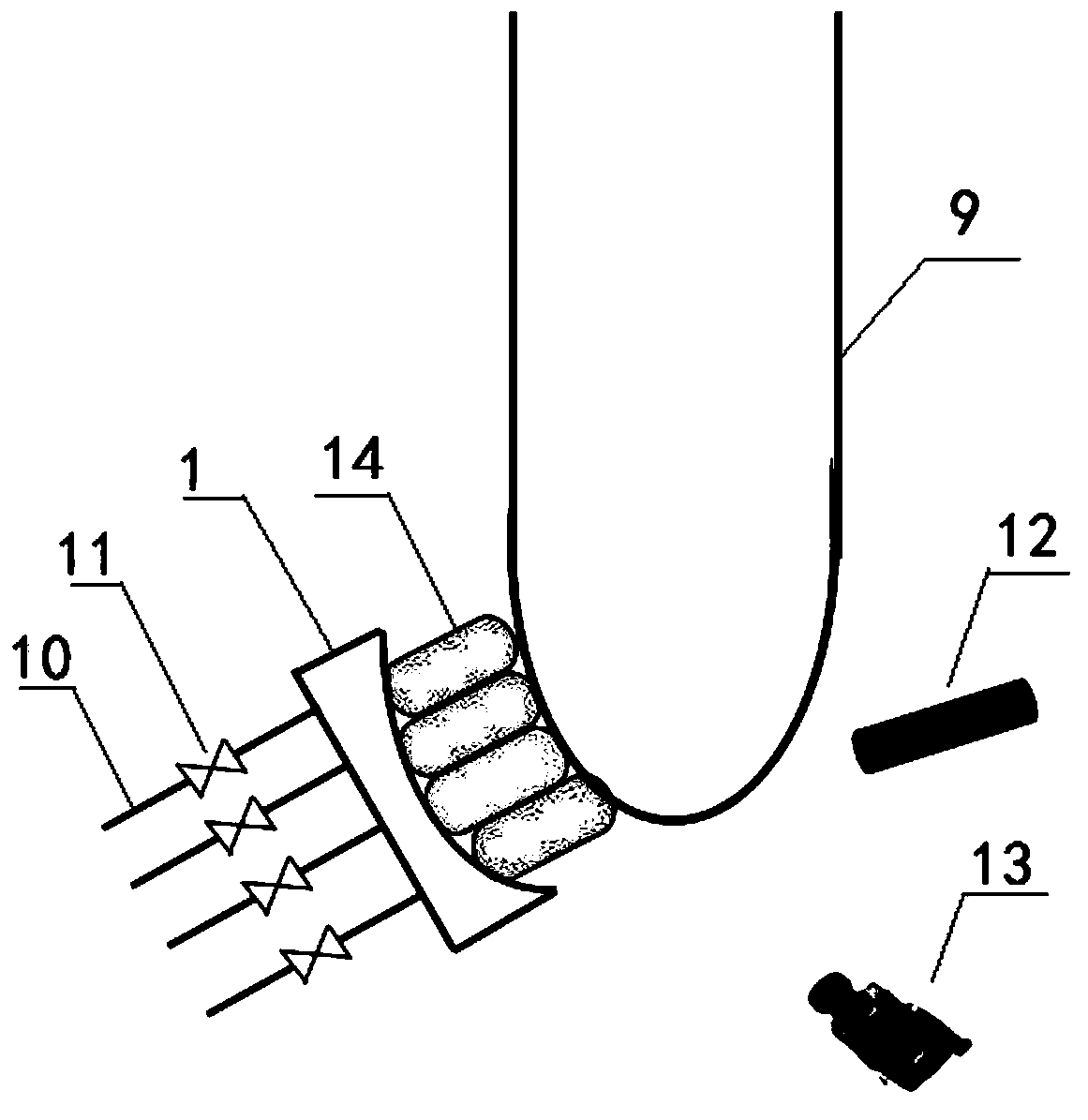
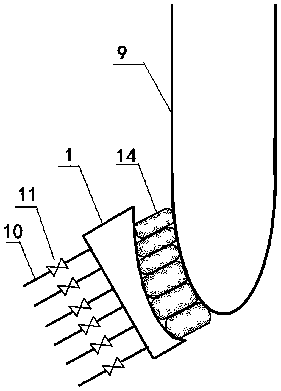
[0047] See figure 1 As shown, the embodiment of the present invention provides a torch suitable for VAD deposition. The difference between this embodiment and Embodiment 1 is that the spray direction of each branch hole included in the feeding hole 2 is roughly the same as the deposition end surface of the powder rod 9 Vertical, when designing the direction of the branch holes, the two ends of the lamp body 1 facing away from the powder stick 9 and facing the powder stick 9 are called the back and the front respectively. All branch holes and the inner isolation pores 3 and the outer isolation pores 8 are A straight hole extending from the back to the front. Taking the branch hole in the middle of the feeding hole 2 as a reference, as the center line, the direction of the branch hole outside the center line in the feeding hole 2 is: when extending from the back to the front, it gradually approaches the center line to ensure the feeding Each supporting hole of the hole 2 is subst...


PUM


Abstract

The invention discloses a blast lamp suitable for VAD deposition, wherein the blast lamp comprises a lamp body; the lamp body is provided with a slotted feed pore and multi-layer annular gas pores around the outer side of the feed pore; the shape of the multi-layer annular gas pores is matched with the shape of the feed pore; the multi-layer annular gas pores include inner-layer isolation gas pores, inner-layer flame pores, outer-layer flame pores and outer-layer isolation gas pores arranged sequentially from inside to outside; the inner-layer flame pores include inner-layer hydrogen pores andinner-layer oxygen pores, and the outer-layer flame pores include outer-layer hydrogen pores and outer-layer oxygen pores; the feed pore, the inner-layer hydrogen pores, the inner-layer oxygen pores,the outer-layer hydrogen pores and the outer-layer oxygen pores are separated to form multiple branch pores respectively; the branch pores, the inner-layer isolation gas pores and the outer-layer isolation gas pores are connected with a gas intake pipeline, and the gas intake pipeline is provided with a flow regulating valve. Continuous regional deposition is adopted, the deposition end face is more smooth and uniform, and the temperature control of the deposition end face is facilitated. With regulation of the hydrogen flow rate in different areas of the outer layer, the temperature field can be uniformed and the cracking and fracture problems of powder rods are reduced.

Description

Technical field [0001] The invention relates to the technical field of optical fiber manufacturing, in particular to a torch suitable for VAD deposition. Background technique [0002] In recent years, with the rapid development of information technology, the general public's demand for data services has continued to increase, and it is particularly important to accelerate the implementation of the "fiber to the home" strategy. The Ministry of Industry and Information Technology emphasized that it will further increase the implementation of the "Broadband China" strategy in the future. As an important information infrastructure, optical fiber, optical cable and optical communication equipment have ushered in a new wave of development. [0003] Optical fiber preform is an important basic material for manufacturing optical fibers and cables, and is a key core technology in the optical fiber production process. At present, the domestic processes for preparing preforms mainly include ...

Claims


Application Information

Patent Timeline
IPC IPC(8): C03B37/014
CPCC03B37/0142C03B2207/16
Inventor 金雾田锦成伍淑坚梁后杰
Owner WUHAN FIBERHOME RUITUO TECH CO LTD
Learn More