
Automatic measuring and cutting device of board

An automatic measurement and cutting device technology, applied in metal processing and other directions, can solve problems such as inability to cut, and achieve the effect of ensuring cutting accuracy

Inactive Publication Date: 2019-04-30
EASTERN GANSU UNIVERSITY
View PDF8 Cites 20 Cited by
  • Summary
  • Abstract
  • Description
  • Claims
  • Application Information

AI Technical Summary

Problems solved by technology

The utility model is provided with a new type of plate automatic cutting equipment, the dust-proof room can not only block the dust, but also avoid the harm caused by the flying of the plate slag, and the horizontal and vertical integration is set, which effectively improves the cutting speed; the utility model The disadvantage is that it is not possible to measure the plate and cut the specified size of the measured plate

Method used


Image

  • Automatic measuring and cutting device of board
  • Automatic measuring and cutting device of board
  • Automatic measuring and cutting device of board

Examples


specific Embodiment approach 1

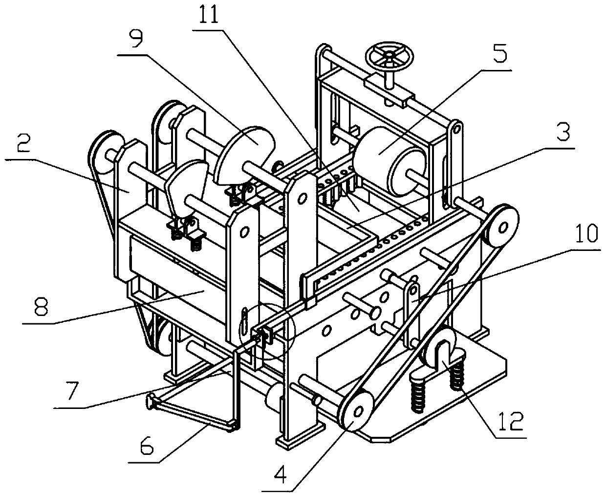
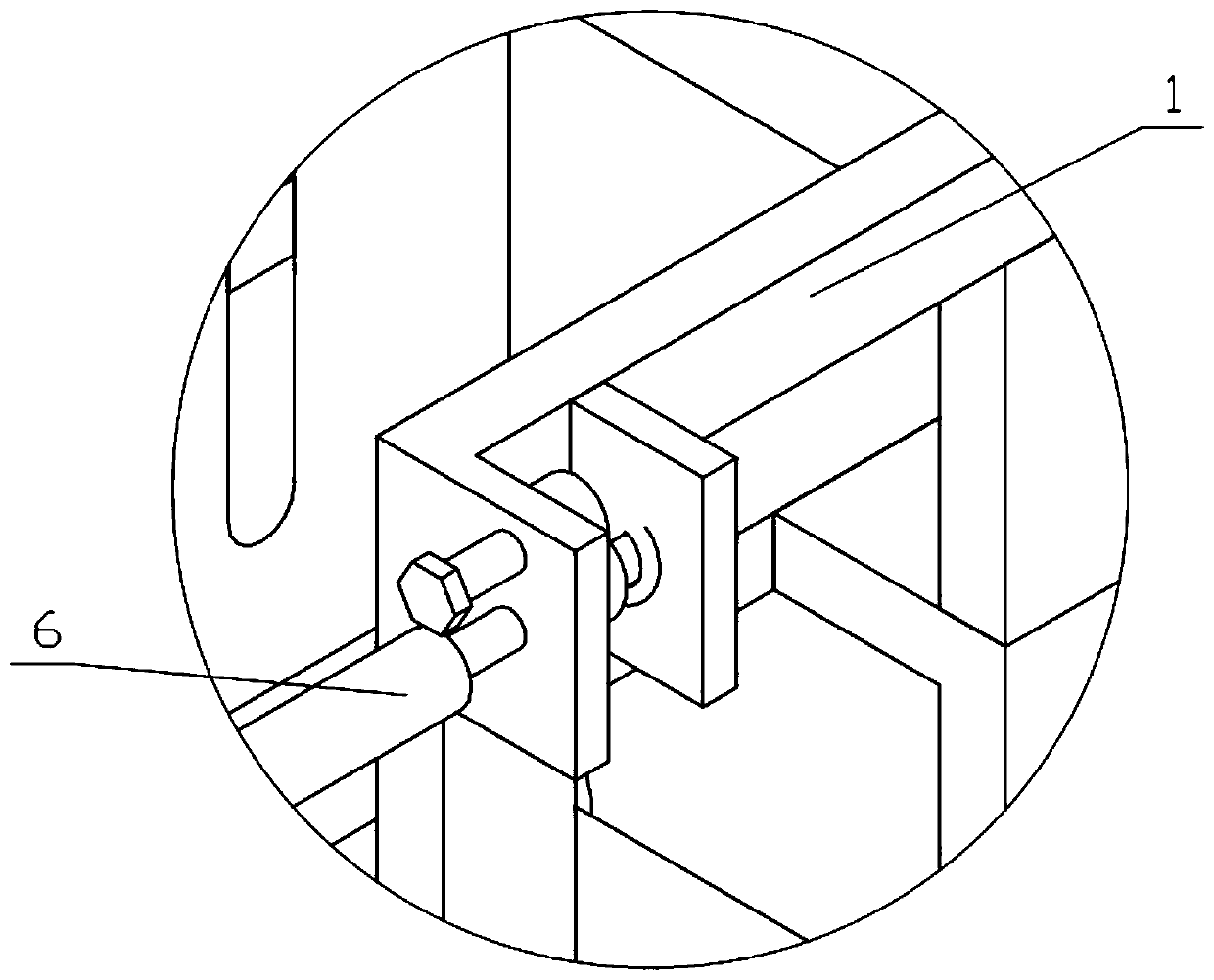
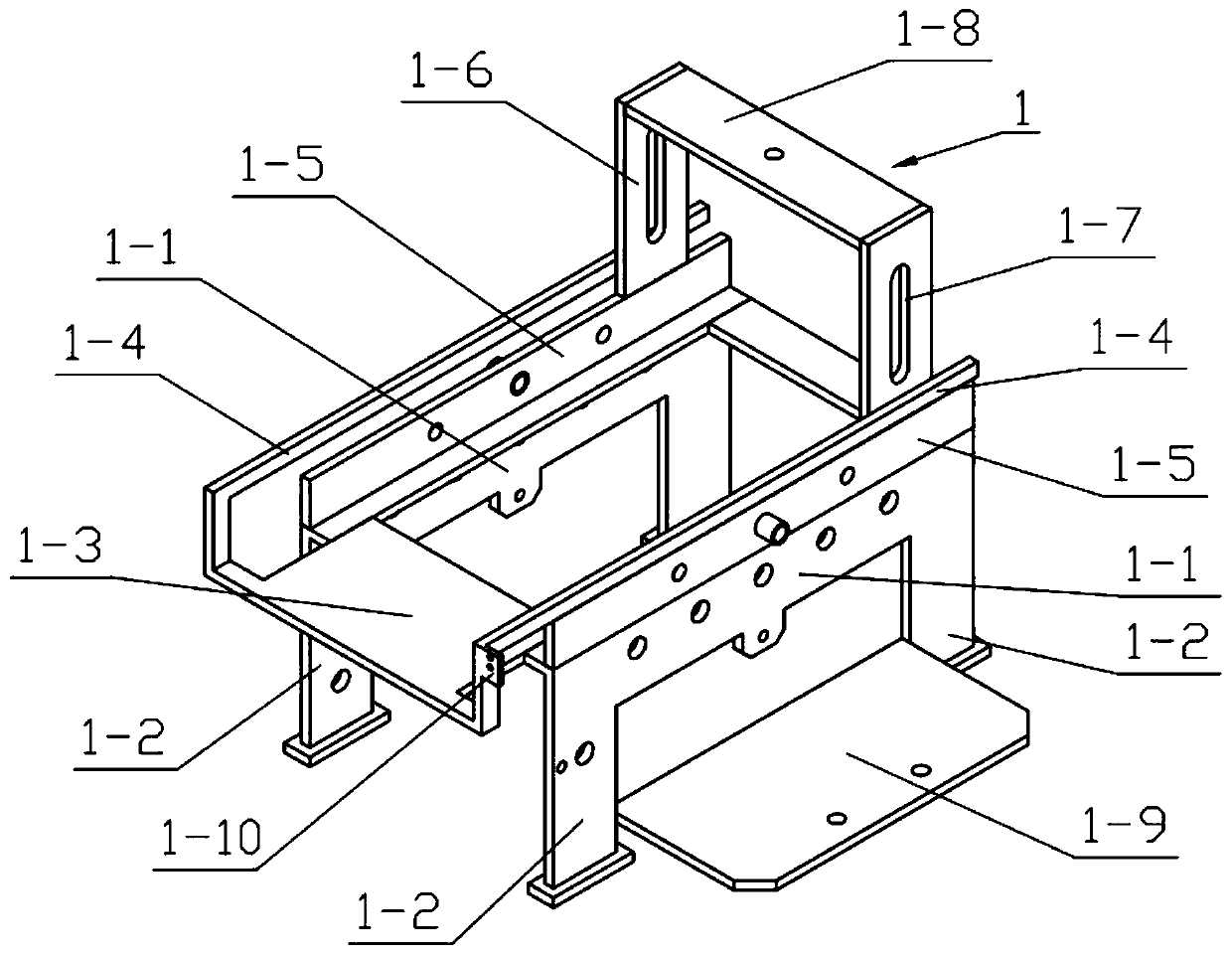
[0041] Combine below Figure 1-15 Describe this embodiment, an automatic measurement and cutting device for plates, including a device support 1, a cutting support 2, a measuring mechanism 3, a power mechanism I4, a pushing mechanism 5, a stop mechanism 6, a power mechanism II7 and a cutting mechanism 8, which can be measured by The two ends of the mechanism 3 are respectively slidably connected to the two measuring rulers 1-4 to measure the plate placed between the two support plates I1-1; The plate between 1 is pushed. When the plate moves the specified distance measured, the measuring mechanism 3 will push the stop mechanism 6 to move, and the stop mechanism 6 will cut off the power on the power mechanism I4, and the push mechanism 5 is not moving. The plate moves to the specified length, and the specified length of the plate is punched and cut through the cutting mechanism 8, and the pressing mechanism 9 clamps the plate during cutting to ensure that there will be no vibra...

specific Embodiment approach 2

[0051] Combine below Figure 1-15 This embodiment will be described, and this embodiment will further describe Embodiment 1. The device bracket 1 further includes a sliding plate 1-9, and the sliding plate 1-9 is fixedly connected between the two supporting feet 1-2 on one side.

specific Embodiment approach 3

[0052] Combine below Figure 1-15 Describe this embodiment, this embodiment will further explain the second embodiment, the cutting bracket 2 also includes a cutting support plate I2-2 and a vertical waist hole III2-7, and the two cutting side plates I2-1 are fixedly connected There is a cutting support plate I2-2, and the lower ends of the two cutting side plates I2-1 are provided with vertical waist holes III2-7.


PUM


Abstract

The invention relates to a cutting device, in particular to an automatic measuring and cutting device of a board. The automatic measuring and cutting device of the board comprises a device supportingframe, a cutting supporting frame, a measuring mechanism, a power mechanism I, a pushing mechanism, a stop mechanism, a power mechanism II and a cutting mechanism, and the two ends of the measuring mechanism are correspondingly and slidably connected to two measuring rulers to measure the board placed between two supporting plates I, the board placed between the two supporting plates I are pushedto move through the pushing mechanism, when a specified distance measured by board movement is measured, the measuring mechanism can push the stop mechanism to move, the stop mechanism cuts off poweron the power mechanism I, and the pushing mechanism does not move, the board moves to a specified length, and the specified length of the board is subjected to stamping and cutting through the cuttingmechanism, a pressing mechanism clamps the board when the cutting is carried out, and no jitter generating when the cutting is carried out can be ensured, and the cutting accuracy is ensured.

Description

technical field [0001] The invention relates to a cutting device, in particular to a plate automatic measuring and cutting device. Background technique [0002] For example, the publication number CN205009315U is a new type of automatic plate cutting equipment, including a dustproof room and a cutting device and a transmission device installed in the dustproof room. One end of the dustproof room is provided with a feed port, and the other end is provided with a Outlet, the cutting device includes a transverse cutting device and a longitudinal cutting device, the transmission device includes a transmission frame and transmission rollers, the transmission rollers are installed on the transmission frame, and the horizontal cutting device is installed on the transmission on the frame, and close to the feed inlet, the longitudinal cutting device is installed on the transmission frame, and close to the discharge port, and the plate is arranged on the transmission rollers. The uti...

Claims


Application Information

Patent Timeline
IPC IPC(8): B26D1/06B26D5/16B26D7/02B26D7/06B26D7/28
CPCB26D1/06B26D5/086B26D5/16B26D7/025B26D7/0608B26D7/28
Inventor 韩娜妮郑祎林
Owner EASTERN GANSU UNIVERSITY
Learn More