
continuous casting method for steel

A technology for casting molds and casting pieces, applied in the field of continuous casting of steel, can solve the problems such as the limitation of the improvement effect of center segregation, and achieve the effect of improving internal quality, preventing cracks, and reducing the part that forms segregation.

Active Publication Date: 2021-12-10
JFE STEEL CORP
View PDF14 Cites 0 Cited by
  • Summary
  • Abstract
  • Description
  • Claims
  • Application Information

AI Technical Summary

Problems solved by technology

[0011] One of them is the soft reduction method of the slab by the reduction roll group, but there is a limit to the improvement effect of the center segregation in the soft reduction to a degree slightly exceeding the solidification shrinkage amount

Method used

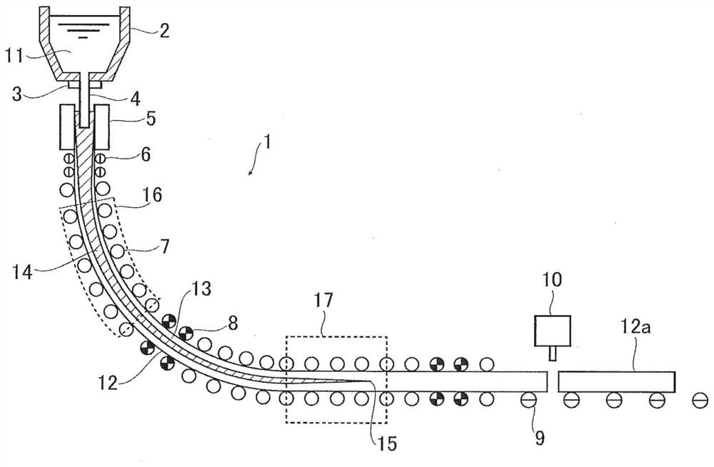
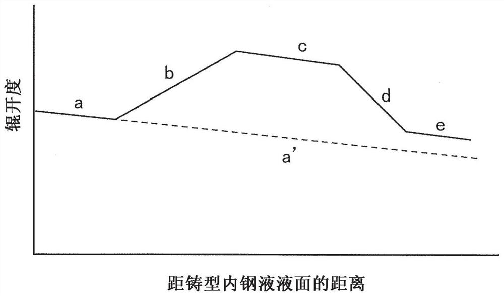
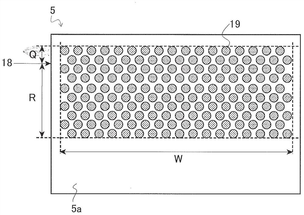

Image

  • continuous casting method for steel
  • continuous casting method for steel
  • continuous casting method for steel

Examples


Embodiment 1

[0120] The following tests were carried out: using a water-cooled copper mold in which metal was placed on the inner wall under various conditions, and various tests were performed on the total belly volume in the forced belly belt and the product of the reduction speed and the casting speed in the soft reduction belt. Change, to cast medium carbon steel (chemical composition, C: 0.08-0.17 mass%, Si: 0.10-0.30 mass%, Mn: 0.50-1.20 mass%, P: 0.010-0.030 mass%, S: 0.005-0.015 mass% , Al: 0.020 to 0.040% by mass), and the surface cracks and internal quality (central segregation) of the cast slab after casting were investigated.

[0121] The product of the reduction speed in the soft reduction zone and the casting speed is 0.28~0.90mm·m / min 2 , in any of the tests, the slab was pressed from the time when the solid fraction in the center of the thickness of the slab was at least 0.2 to the time when it became 0.9 for the soft reduction zone. When the cast slab is forcibly bulged b...


PUM

PropertyMeasurementUnit
thicknessaaaaaaaaaa
solid fractionaaaaaaaaaa

Abstract

The present application provides a continuous casting method for steel, the ratio of which is 20% or more to provide the inner wall surface of the continuous casting mold copper plate (5a) filled with the thermal conductivity difference with respect to the mold copper plate The technology of the different heat conduction metal filling part (19) of the metal is to prevent the solidification during continuous casting by making the interval in the width direction and the interval in the casting direction of the different heat conduction metal filling part a value specified by a predetermined formula or less. Surface cracks caused by uneven cooling of the initial solidified shell suppress central segregation at the center of the thickness of the slab.

Description

technical field [0001] The present invention relates to continuous casting technology, and in particular to a continuous casting method for steel suitable for improving surface cracks and center segregation of slabs by suppressing uneven solidification of slabs in the initial stage of solidification. Background technique [0002] Generally, when producing steel slabs by continuous casting, molten steel poured into the mold first contacts the mold and cools to form a thin solidified layer (hereinafter referred to as "solidified shell"). In this way, the solidified shell is drawn downward while pouring molten steel into the mold (hereinafter referred to as "stabilized casting") to manufacture a cast slab. [0003] If the cooling of the mold is not uniform, the thickness of the solidified shell is not uniform, and as a result, the surface of the solidified shell is not smooth. In particular, if the thickness of the solidified shell grows non-uniformly in the initial stage of s...

Claims


Application Information

Patent Timeline
Patent Type & Authority Patents(China)
IPC IPC(8): B22D11/04B22D11/059B22D11/128B22D11/16B22D11/20
CPCB22D11/04B22D11/059B22D11/128B22D11/16B22D11/20
Inventor 荒牧则亲古米孝平三木祐司
Owner JFE STEEL CORP
Learn More