A uniform coal feeding device for a three-waste mixed combustion furnace
A technology of coal feeding device and co-combustion furnace, which is applied in the direction of adjusting fuel supply, controlling combustion, fuel supply, etc., and can solve the problems of increasing the wear and tear of the spiral coal feeding auger and coal feeding resistance, hidden dangers of coal machine safe operation, and difficulty in maintaining temperature Housing and other issues, to achieve the effect of reasonable layout of coal combustion, shortened combustion time, and easier temperature control
- Summary
- Abstract
- Description
- Claims
- Application Information
AI Technical Summary
Problems solved by technology
Method used
Image
Examples
Embodiment 1
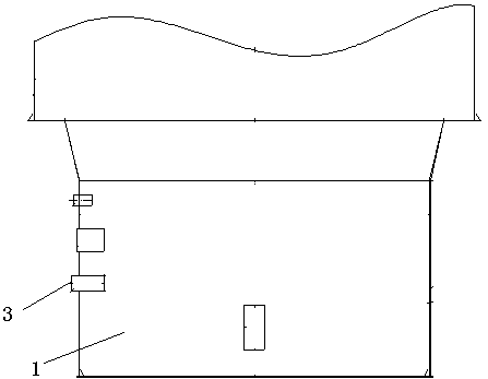
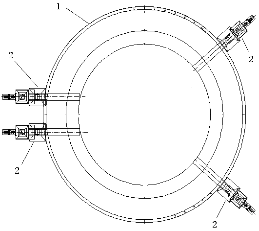
[0026] Such as figure 1 , 2 As shown, this embodiment provides a uniform coal feeding device for a three-waste mixed combustion furnace, including a mixed combustion furnace 1 and a coal feeder 2, and the coal feeder 2 transports the coal material to the mixed combustion furnace 1. The left side of described co-combustion furnace 1 is provided with two coal feeding ports 3, and the right side of described co-combustion furnace is also provided with two coal feeding ports 3 simultaneously, and each described coal feeding port 3 is all connected with Coal feeder 2, the height of the coal feed port 3 is higher than the horizontal center point height of the co-combustion furnace 1. In the present embodiment, the height of the coal inlet is 1900mm, and the diameter of the combustion furnace hearth is Φ6000mm.
[0027] In the production of the three-waste mixed combustion furnace, the coal is evenly sprinkled into the furnace, and burned under the heating of the high-temperature s...
Embodiment 2
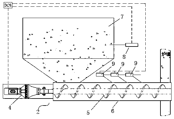
[0030] Such as image 3 As shown, the coal feeder 2 includes a motor 4 and an auger 5, the motor 4 drives the auger 5 to run, and the outer side of the auger 5 is covered with a closed sleeve 6, and the sleeve 6 6 top is provided with coal bunker 7. The coal bunker 7 is provided with a humidity sensor 8, and the sleeve 6 is provided with an electromagnetic pneumatic injection valve 9 every 400 mm. The motor 4, the humidity sensor 8 and the electromagnetic pneumatic injection valve 9 are all connected to the PLC on the controller. The air source of the electromagnetic pneumatic blowing valve 9 is supplied by instrument air, and the pressure is 0.6MPa. The electromagnetic pneumatic blowing valve 9 includes three working modes, namely low frequency mode, intermediate frequency mode and high frequency mode. In the low-frequency mode, the injection time interval is 100s, and each injection time is 0.3s, indicated by a yellow indicator light. In the intermediate frequency mode, ...
PUM
 Abstract
Description
Claims
Application Information
 - Generate Ideas
- Intellectual Property
- Life Sciences
- Materials
- Tech Scout
- Unparalleled Data Quality
- Higher Quality Content
- 60% Fewer Hallucinations
Browse by: Latest US Patents, China's latest patents, Technical Efficacy Thesaurus, Application Domain, Technology Topic, Popular Technical Reports.
© 2025 PatSnap. All rights reserved.Legal|Privacy policy|Modern Slavery Act Transparency Statement|Sitemap|About US| Contact US: help@patsnap.com


