Leaching machine

A technology of leaching and reducer, which is applied in the field of extraction, can solve the problems of easy detachment of chain transmission, chain pins falling off, unavoidable contact, etc., and achieve the effect of simplified transmission, stable operation and elimination of potential safety hazards

Pending Publication Date: 2019-04-16
ANHUI PROVINCE YINGSHANG COUNTY SANJIN GRAINS ANDOILS CO LTD
View PDF0 Cites 0 Cited by
  • Summary
  • Abstract
  • Description
  • Claims
  • Application Information

AI Technical Summary

Problems solved by technology

[0004] However, in the prior art, the horizontal-rotation leaching machine mostly adopts a chain transmission system, the chain transmission is easy to disengage the chain, and the chain is broken. In addition, the outside of the chain pin is prone to slipping off, and the chain is bitten by the gear. The maintenance process It is necessary to open the extractor in the process, and the process will inevitably come into contact with the solvent mixture or its volatile gas, which has certain dangers. In addition, the economic loss caused by downtime and maintenance is very large.

Method used


Image

  • Leaching machine
  • Leaching machine
  • Leaching machine

Examples


Embodiment 1

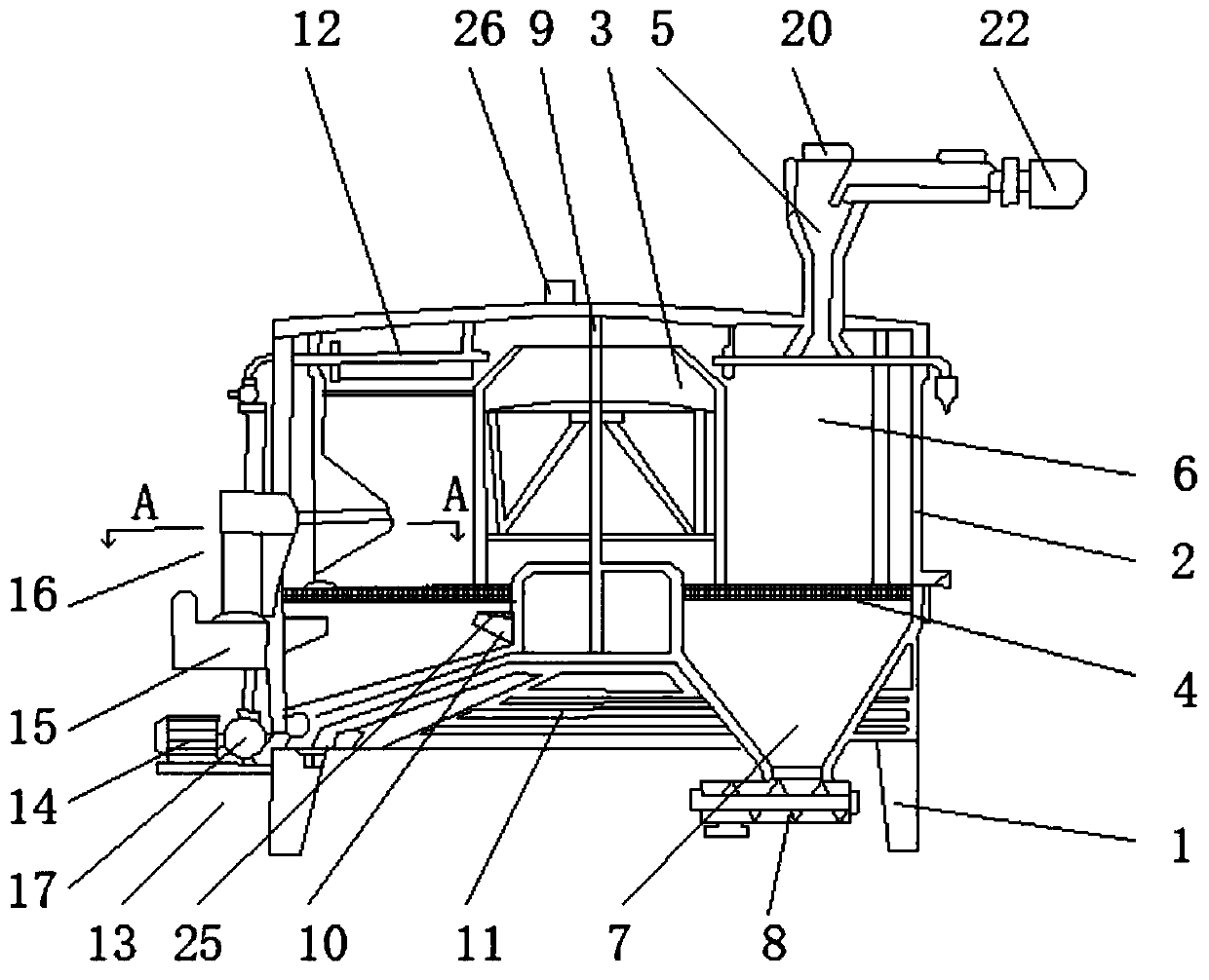
[0025] Such as Figure 1-3 As shown, a leaching machine includes a base 1, a housing 2, and a reaction chamber 3. A housing 2 is fixedly installed on the base 1. A reaction chamber 3 is arranged at the upper end of the housing 2 near the middle, and a horizontal chamber 3 is arranged below the reaction chamber 3. There is a fixed grid bottom 4, the two ends of the fixed grid bottom 4 are fixedly connected on the inner wall of the housing 2, the upper end of the housing 2 is provided with a feed port 5 near one side, and the lower end of the feed port 5 is connected with a rotating body 6, The rotating body 6 is located above the fixed grid bottom 4, the lower end of the rotating body 6 is connected with a meal output box 7, and the lower end of the meal output box 7 is connected with a meal output screw conveyor 8, and the middle of the reaction chamber 3 is vertically provided with a rotating shaft 9, The lower end of the reaction chamber 3 is connected with an oil outlet 10,...

Embodiment 2

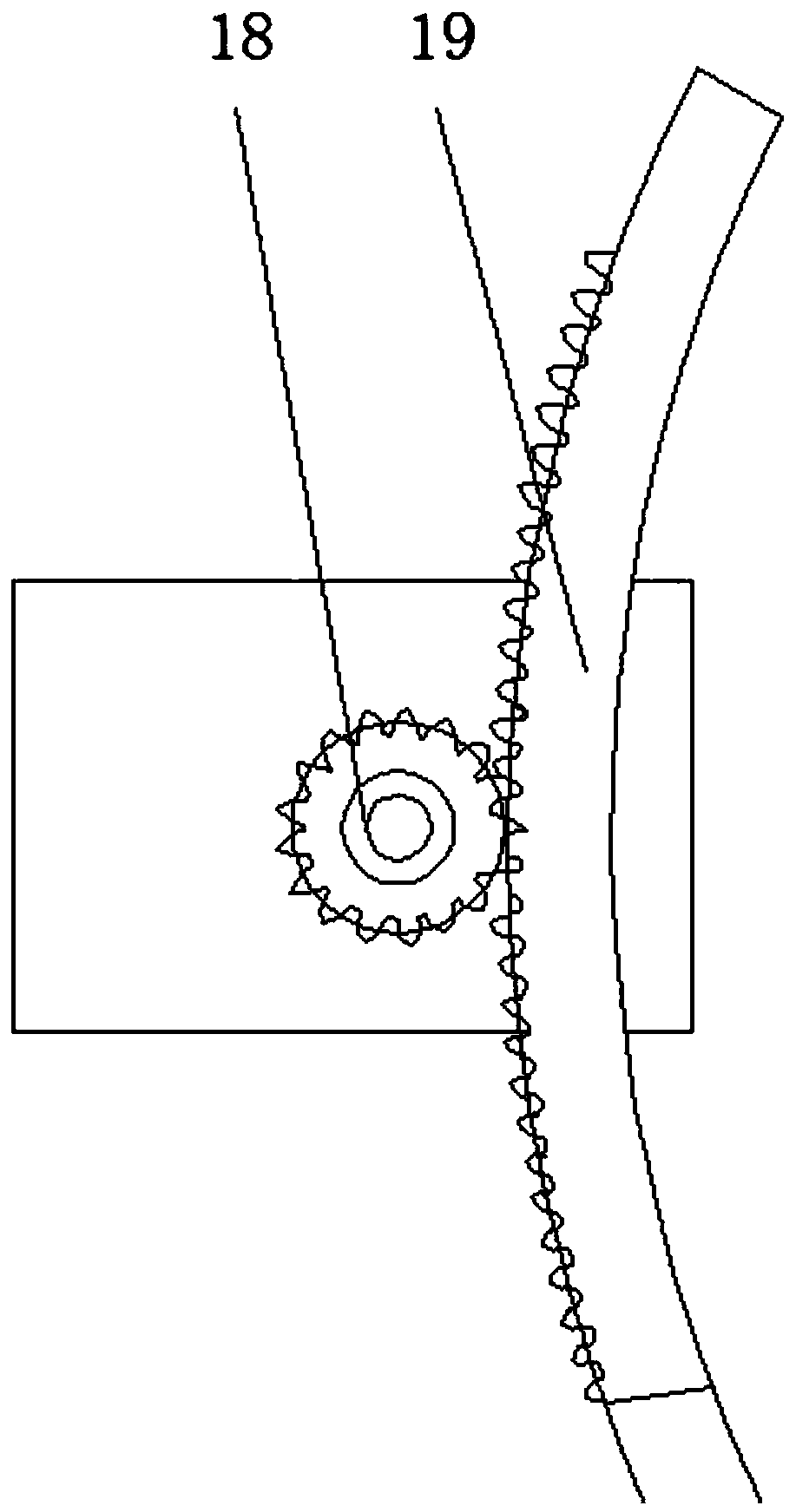
[0030] Such as Figure 1-3 As shown, a leaching machine, the transmission device 13 includes a motor 14, a reducer 15 and a transmission gear set 16, the output end of the motor 14 is connected with the input end of the reducer 15 through a mixing oil pump 17, and the output end of the reducer 15 is connected to the transmission The gear set 16 is connected, the transmission gear set 16 includes a driving pinion 18 and a driven bull gear 19, the output end of the reducer 15 is connected with the driving pinion 18, the driving pinion 18 meshes with the driven bull gear 19, and the driven bull gear 19 is connected with rotating shaft 9 by chain.

[0031] Further, the speed reducer 15 is a two-stage pendulum speed reducer with an extended shaft.

[0032] It should be noted that, the gear transmission system is adopted, the transmission box tensioning device of the prior art is canceled, the transmission device 13 is simplified, and the moving parts are reduced; the straight toot...

Embodiment 3

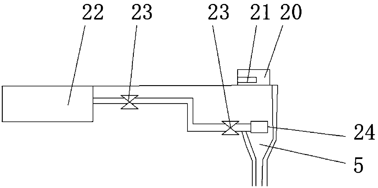
[0034] Such as Figure 1-3 Shown, a kind of leaching machine, feeding port 5 places are provided with sight glass 20, and the side near sight glass 20 in feeding port 5 is provided with sight glass cleaning device, and sight glass cleaning device comprises siphon big rinsing box 22, Valve 23 and shower nozzle 24, the water outlet of siphon large rinse tank 22 is connected with shower nozzle 24 by water pipe, the water outlet place of siphon large rinse tank 22 and the water inlet place of shower nozzle 24 are all provided with valve 23, and shower nozzle 24 is arranged on Below the mirror 20.

[0035] Further, a scraper 21 is provided on the viewing mirror 20 .

[0036] The feed port 5 is provided with a sight glass 20, which is convenient for the staff to observe the inside of the feed port 5, but the inner wall of the sight glass 20 is often stuck with some meal powder and dust, which will affect the operation of the leaching machine. It is inconvenient. By installing the ...


PUM


Abstract

The invention discloses a leaching machine. The leaching machine comprises a base, a casing and a reactor chamber; the reactor chamber is formed in the portion, close to the middle, of the upper end in the casing, a fixed grid bottom is arranged horizontally below the reactor chamber, the portion, close to one side, of the upper end of the casing is provided with a feeding port, a rotating body isconnected to the lower end of the feeding port and located above the fixed grid bottom, a meal discharging box is connected to the lower end of the rotating body, and a meal discharging screw conveyor is connected to the lower end of the meal discharging box; a rotating shaft is vertically arranged in the middle of the reactor chamber, an oil outlet is connected to the lower end of the reactor chamber, and the lower end of the oil outlet is provided with a plurality of mixed oil collecting cases; the upper portion of the side, away from the feeding port, of the reactor chamber is provided with a mixed oil sprinkling head, the side, close to the mixed oil sprinkling head, of the casing is provided with a transmission device, and an output end of the transmission device is connected with arotating shaft. The leaching machine is simple and compact in structure, by adopting a gear transmission system, the leaching machine runs stably, the hidden safety hazards are eliminated, and the production cost is reduced.

Description

technical field [0001] The invention relates to the technical field of extraction, in particular to an extraction machine. Background technique [0002] Leaching is called extraction in chemical unit operation, and it is widely used in industrial sectors such as chemical industry, food, metallurgy, medicine, feed and oil preparation. The so-called oil extraction is to use the principle that a selected organic solvent can be miscible with oil, soak or spray the processed material blank or pre-pressed cake in an extractor with a solvent, and then mix the obtained oil, Grease is obtained by separating and processing according to their different boiling points. This oil-making process is called oil leaching. [0003] The horizontal rotary leaching machine is the most widely used leaching machine in our country. The horizontal rotary leaching machine has a material partition, and the concentration of the mixed oil in the two leachings before and after the two leachings is less m...

Claims


Application Information

Patent Timeline
Patent Type & Authority Applications(China)
IPC IPC(8): C11B1/10
CPCC11B1/102C11B1/10
Inventor 金荣珍
Owner ANHUI PROVINCE YINGSHANG COUNTY SANJIN GRAINS ANDOILS CO LTD
Why Eureka
Try Eureka