
A device for gas impact coupling porous roof stamping

A technology of gas pressure stabilization and top plate, which is applied in the direction of measuring devices, instruments, particle and settlement analysis, etc., can solve the problems of long vibration time, waste of product quality, impact, etc., and achieve the effect of strong applicability

Active Publication Date: 2020-09-15
NORTHEASTERN UNIV LIAONING
View PDF1 Cites 0 Cited by
  • Summary
  • Abstract
  • Description
  • Claims
  • Application Information

AI Technical Summary

Problems solved by technology

However, the noise generated by vibration is large, segregation is easy to occur for multi-component particles, and the vibration time to achieve densification is long; during the pressing process, since the force is mainly concentrated near the pressing plate, it is easy to cause uneven distribution of the packing density of the particles, resulting in a higher density at the top. Large defects; during the gas impact process, due to the difference in the degree of freedom of the particles at different heights of the piled material column, it is easy to form a gradient difference in which the density at the bottom of the material column is greater than that at the top, and the particle layer at the top is affected by the gas impact process. The initial instantaneous gas impact forms an uneven material layer and even some particles splash, resulting in waste and a greater impact on product quality

Method used


Image

  • A device for gas impact coupling porous roof stamping
  • A device for gas impact coupling porous roof stamping
  • A device for gas impact coupling porous roof stamping

Examples


Embodiment 1

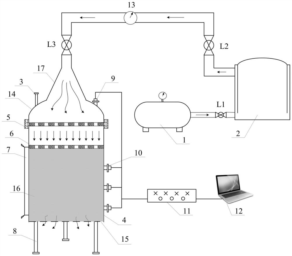
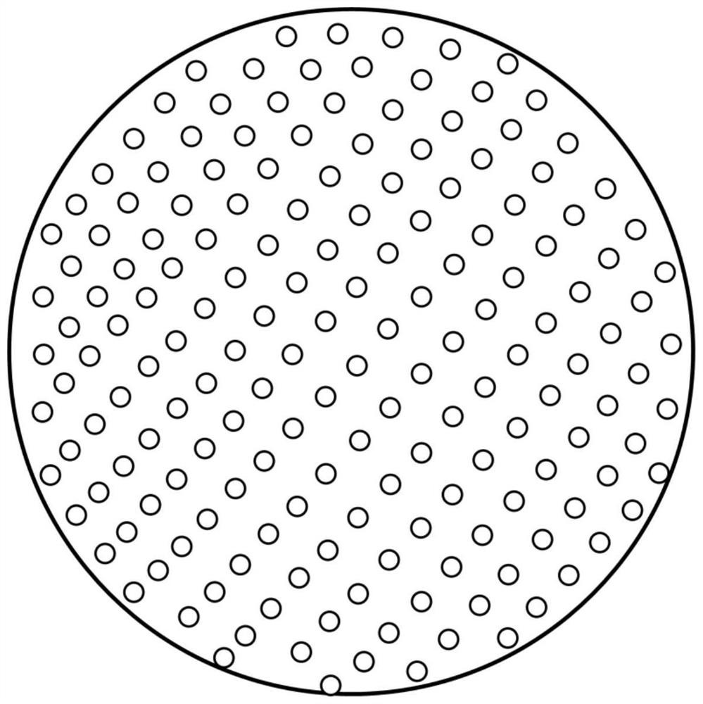
[0055] A gas impact coupled porous top plate stamping device to achieve particle packing densification, such as figure 1 As shown, it mainly includes an air compressor 1, a gas storage tank 2, a cylinder body 4, legs 8, an upper head 14, a movable porous top plate 6, an air pressure sensor and a pressure sensor. The air compressor 1 is connected to the gas stabilizing storage tank 2 through pipelines, and the gas stabilizing storage tank 2 is connected to the cylinder body 4 through pipelines. The inside of the cylinder body 4 is used to place particles that need to be Into the inside of the cylinder 4, the size of the movable porous top plate 6 is as large as the cross-sectional area of ​​the cylinder body. The movable porous top plate 6 is provided with a plurality of through holes, and the upper end of the cylinder 4 passes through the flange 5 and the upper head 14. Sealed connection, an air inlet 17 is provided in the center of the top of the upper head 14, the gas storag...

Embodiment 2

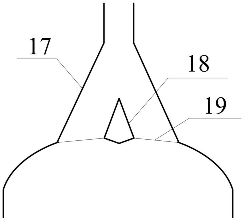
[0069] This embodiment is based on Embodiment 1, and a gas diversion cone 18 is fixedly installed directly below the air inlet in the air inlet 17, and the diversion cone is fixed by a diversion cone bracket 19. The schematic diagram is as follows image 3 As shown, the guide cone bracket 19 is fixed inside the upper head 14 .

[0070] When the high-pressure gas flows through the diversion cone 18 for diversion, it acts on the movable porous roof and quickly flows through the impacting particle medium. Various particles are piled up and densified under the impact of the high-pressure gas, and finally the gas is discharged through the openings at the bottom. Further avoiding the formation of pits on the surface of the particle densification layer due to excessive local pressure caused by uneven gas distribution.

[0071] The movable porous roof of the present invention not only provides a certain gravity for pressing the particles, but also provides mechanical pressure under th...


PUM

PropertyMeasurementUnit
pore sizeaaaaaaaaaa

Abstract

The invention relates to a device for gas impact coupled porous top plate stamping, which is used to achieve particle accumulation and densification. It includes an air compressor, a gas pressure stabilizing storage tank, a cylinder, an upper head, a movable porous top plate, legs and a pressure sensor. ; Among them, the air compressor is connected to the gas pressure-stabilizing storage tank, the gas pressure-stabilizing storage tank is connected to the cylinder, the movable porous top plate can be movably placed inside the cylinder, and the upper end of the cylinder is sealed and connected with the upper head. The top of the head is provided with an air inlet, and the gas pressure stabilizing storage tank is connected to the air inlet through a pipeline; the side wall of the cylinder is provided with a perspective window with scales; the lower end of the cylinder is provided with legs, and the cylinder The bottom surface is provided with multiple openings. This device realizes the dense accumulation of particles, eliminates the density gradient defects in the axial accumulation of material columns caused by the simple pressing process or gas impact process, realizes a fast and efficient particle accumulation and densification process, and the accumulation structure is uniform and dense. Have good work efficiency.

Description

technical field [0001] The invention relates to a device for gas impact coupling porous top plate stamping, which belongs to the technical field of physical experiment equipment. Background technique [0002] Particle packing and densification has been widely used in energy, chemical, metallurgy, construction and other industries. To achieve fast and efficient particle packing densification, more stringent requirements are put forward for particle packing density and arrangement. At present, there are three main ways to achieve particle accumulation and densification: vibration, compression and gas impact. However, the noise generated by vibration is large, segregation is easy to occur for multi-component particles, and the vibration time to achieve densification is long; during the pressing process, since the force is mainly concentrated near the pressing plate, it is easy to cause uneven distribution of the packing density of the particles, resulting in a higher density a...

Claims


Application Information

Patent Timeline
Patent Type & Authority Patents(China)
IPC IPC(8): G01N15/02G01N15/00
CPCG01N15/00G01N15/02
Inventor 安希忠韦光超勾大钊张浩于传伟付海涛杨晓红
Owner NORTHEASTERN UNIV LIAONING
Learn More