Narrowband reflective film
A reflective film, narrow-band technology, applied in the field of narrow-band reflective film, can solve the problem of large reflection bandwidth of reflective film
- Summary
- Abstract
- Description
- Claims
- Application Information
AI Technical Summary
Problems solved by technology
Method used
Image
Examples
Embodiment 1
[0070] Simulation experiment data:
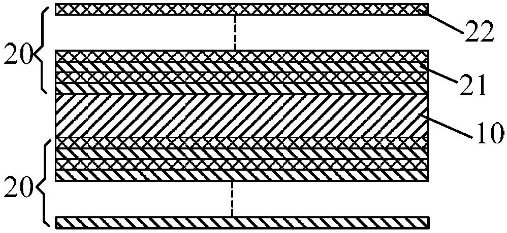
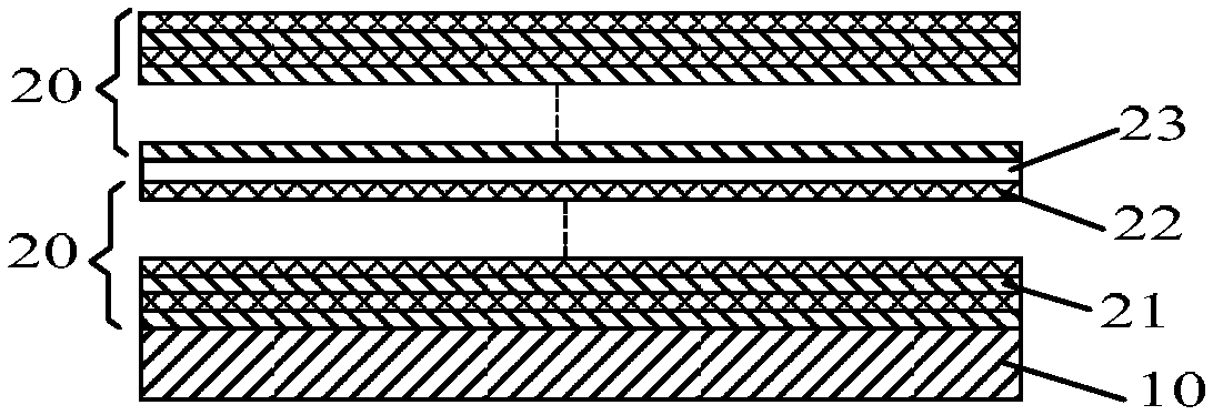
[0071] On the PET layer with a thickness of 0.05mm, an anti-reflection layer and a reflective film system (a layer of high refractive index material and a layer of low refractive index material are cross-stacked), wherein the center wavelength of the incident light is set to 532nm, and the high refractive index The index material layer is a titanium dioxide layer with a refractive index of 2.354, and the low refractive index material layer is a silicon dioxide layer with a refractive index of 1.46, wherein the antireflection layer is composed of a titanium dioxide layer and a silicon dioxide layer with an optical thickness of λ / 4, The optical thickness coefficient of the reflective film system is designed as:
[0072] 第一半膜堆:0.216H 1.836L 0.303H 1.691L 0.377H 1.591L 0.561H 1.501L0.583H 1.422L 0.677H 1.358L 0.762H 1.259L 0.851H 1.192L 0.928H 1.102L 1.010H1.020L 1.106H 0.921L 1.184H 0.886L 1.255H 0.767L 1.346H 0.714L 1.444H 0.634L1.552H 0.564...
Embodiment 2
[0077] The two half-film stacks of the narrow-band reflective film corresponding to Example 1 were fabricated by using the magnetron sputtering process, and the substrate (with a 0.05mm PET layer on the substrate) was cleaned with a clean cloth and ethanol. After degassing the vacuum chamber, use a vacuum cleaner to clean the inside of the bell jar, fill the molybdenum boat with the film material to be evaporated, and record the name of the film material of each boat. And place the substrate on the substrate frame, do not tilt the substrate. Drop the bell jar and evacuate the vacuum chamber according to the operation rules of the coating machine. When the vacuum reaches 7×10 -3 After Pa, pre-melt the film material in the molybdenum boat in turn to remove the gas in the film material. At this time, pay attention to block the film material with a baffle to ensure that the substrate will not be plated during pre-melting. When the vacuum degree reaches the requirement, the meth...
Embodiment 3
[0080] Simulation experiment data:
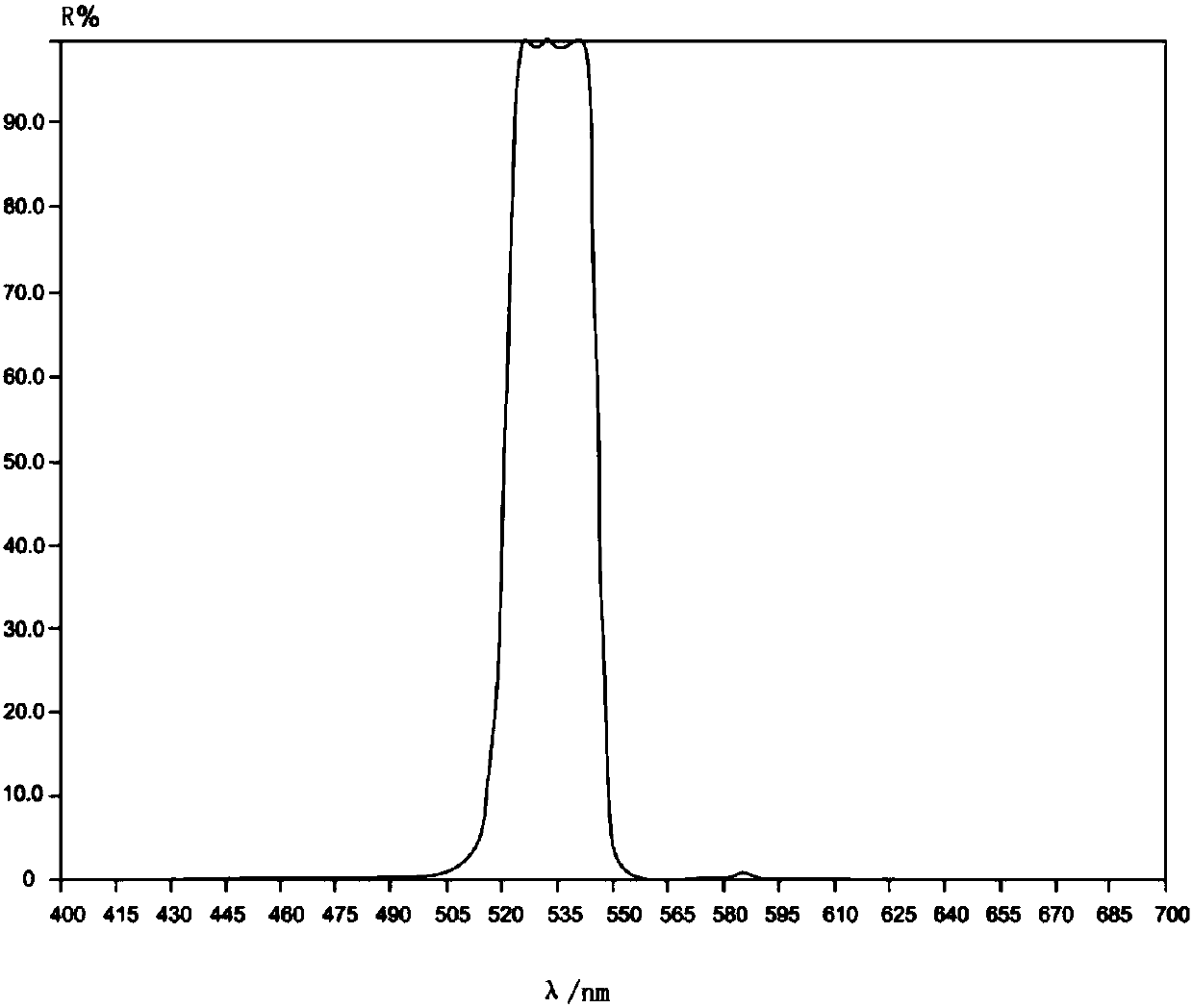
[0081] The optical thickness coefficient of the high-refractive index material layer and the optical thickness coefficient of the low-refractive index material layer of the film system are the same as in Example 1, and the two half-film stacks are arranged on two opposite surfaces of the PET layer. Use the Essential Macleod film system design software to simulate the light reflection performance of the above-mentioned narrow-band reflective film, and the simulation results are shown in Image 6 and Table 1.
PUM
| Property | Measurement | Unit |
|---|---|---|
| Physical thickness | aaaaa | aaaaa |
| Thickness | aaaaa | aaaaa |
| Thickness | aaaaa | aaaaa |
Abstract
Description
Claims
Application Information
 - R&D
- Intellectual Property
- Life Sciences
- Materials
- Tech Scout
- Unparalleled Data Quality
- Higher Quality Content
- 60% Fewer Hallucinations
Browse by: Latest US Patents, China's latest patents, Technical Efficacy Thesaurus, Application Domain, Technology Topic, Popular Technical Reports.
© 2025 PatSnap. All rights reserved.Legal|Privacy policy|Modern Slavery Act Transparency Statement|Sitemap|About US| Contact US: help@patsnap.com


