
Uniform light shooting device used for there-dimensional digital microscope

A technology of digital microscopes and shooting devices, which is applied in the field of testing and inspection, and can solve the problems that the details of bright spots and dark places cannot be displayed, and the over-exposed and under-exposed areas where the shape cannot be observed, so as to avoid specular reflection phenomenon, the effect of improving image quality

Inactive Publication Date: 2019-04-05
CHINA HANGFA GUIZHOU LIYANG AVIATION POWER CO LTD
View PDF5 Cites 1 Cited by
  • Summary
  • Abstract
  • Description
  • Claims
  • Application Information

AI Technical Summary

Problems solved by technology

[0003] When there are mirrors (macro mirrors or micron mirrors) in the object to be photographed, such as processed bright metal parts, fractures of cleavage fractures, cast iron fractured along the graphite phase, etc., only mirrors with specific angles on these objects can illuminate the light source The light is reflected into the CCD for imaging, so the captured image will have overexposed and underexposed areas where the morphology cannot be observed
The ratio of the brightness of the overexposed area to the brightness of the underexposed area is 10^8, and the range that human eyes can see is about 10^5, but the general display and CCD can express only 256 different Brightness, even with HDR technology, details in bright spots and dark places cannot be shown on the captured image

Method used


Image

  • Uniform light shooting device used for there-dimensional digital microscope

Examples


Embodiment Construction

[0017] The technical solution of the present invention is further described below, but the scope of protection is not limited to the description.

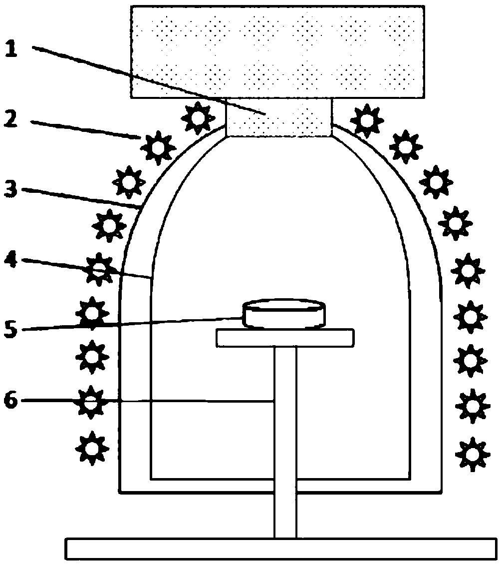
[0018] Such as figure 1 As shown, a uniform light shooting device for a three-dimensional digital microscope includes an LED light 2, an outer diffusion shed 3, an inner diffusion shed 4 and a stage 6, wherein the outer diffusion shed 3 and the inner diffusion shed 4 are both It has a bell-shaped structure and is made of semi-transparent materials; the inner diffusion shed 4 is installed inside the outer diffusion shed 3, and the tops of the outer diffusion shed 3 and the inner diffusion shed 4 are equipped with round holes, and the microscope lens 1 is embedded in the round holes There are multiple LED light lamps 2, which are arranged outside the outer diffusion shed 3; the stage 6 is placed in the inner diffusion shed 4, and when shooting, the object 5 to be photographed is placed on the stage for shooting.

[0019] Further, th...


PUM


Abstract

The invention discloses a uniform light shooting device used for a three-dimensional digital microscope. The device comprises LED (Light Emitting Diode) light lamps, an external diffusion shed, an internal diffusion shed and an objective table, wherein the internal diffusion shed is installed in the external diffusion shed; the top of the internal diffusion shed and the top of the external diffusion shed are independently provided with a round hole; a microscope lens is embedded into the round holes; the plurality of LED light lamps are arranged out of the external diffusion shed; and the objective table is arranged in the internal diffusion shed, and during shooting, an object to be shot is placed on the objective table to be shot. Through the implementation of the invention, the diffusereflection of multiple rays can be formed in a shooting environment, then, the object to be shot is placed in the diffusion shreds to be shot, a mirror reflection phenomenon of the surface of the object can be favorably avoided, the luminance ratio of the light spot and the black spot of the shot object can be greatly reduced, a 360-degree omnibearing no-dead-angle ambient light source can be provided, imaging quality is greatly improved, good support is provided for requirements including subsequent scientific researches, and the device can be prompted and used in a scene which needs to carryout mcroscopic shooting.

Description

technical field [0001] The invention belongs to the technical field of testing and detection, and in particular relates to a uniform light shooting device for a three-dimensional digital microscope. Background technique [0002] At present, in failure analysis or other applications, when obtaining high-magnification optical images of objects, 3D digital video microscopes or stereo microscopes equipped with CCD are often used for shooting. At present, the light sources used by these two types of microscopes are mostly illuminated from top to bottom. LED ring light. The image is mainly imaged by the reflection of the microscope light source, and its reflection follows the law of light reflection. When the object to be photographed is relatively flat (non-mirror), the light is diffusely reflected on the surface of the object, and the light that conforms to the law of reflection of light can smoothly enter the CCD for imaging ; When the object to be photographed is uneven, the ...

Claims


Application Information

Patent Timeline
IPC IPC(8): G02B21/36G02B21/06G03B15/06G03B15/07G03B30/00
CPCG02B21/06G02B21/362G03B15/06G03B15/07
Inventor 杨玉川李永斌陈昌达熊勇汤浩
Owner CHINA HANGFA GUIZHOU LIYANG AVIATION POWER CO LTD
Learn More