
Cathode vibration device for electrolytic machining

A vibrating device and cathode technology, which is used in machining electrodes, electric machining equipment, electrode manufacturing, etc., can solve problems such as stray corrosion, electrolytic machining cannot be carried out normally, and affecting machining accuracy.

Inactive Publication Date: 2019-04-05
CHANGZHOU INST OF TECH
View PDF6 Cites 3 Cited by
  • Summary
  • Abstract
  • Description
  • Claims
  • Application Information

AI Technical Summary

Problems solved by technology

During the machining process, the gap is filled with electrolyte, because all the products dissolved in the electrolytic machining anode are dissolved in the electrolyte, if the electrolyte in the machining gap cannot be updated in time, the electrolytic machining cannot be carried out normally, and even a short circuit will occur in the small gap machining
On the other hand, DC power electrolytic machining will produce stray corrosion, so that electrolytic machining will also occur in parts that do not need to be processed, seriously affecting the machining accuracy

Method used

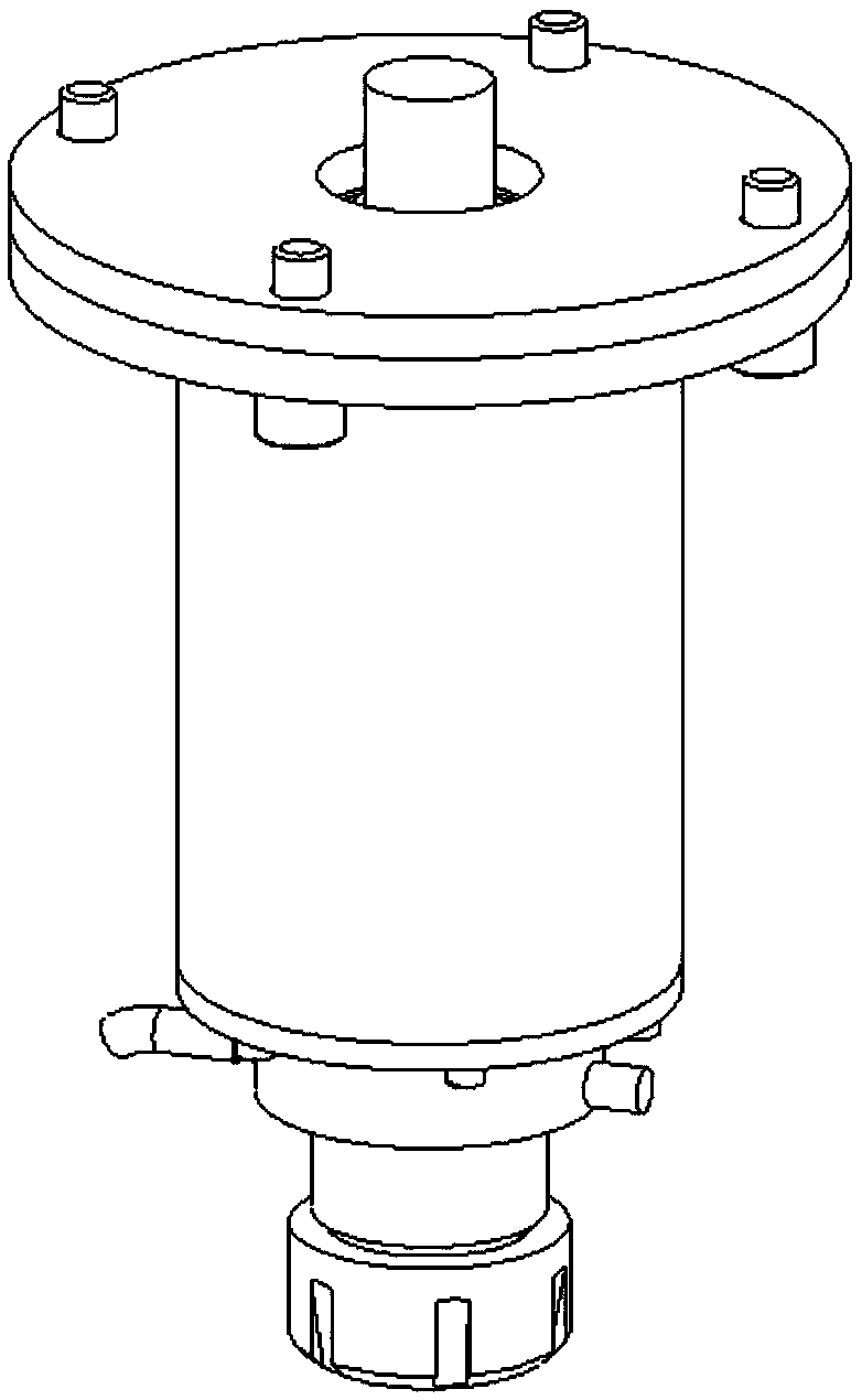
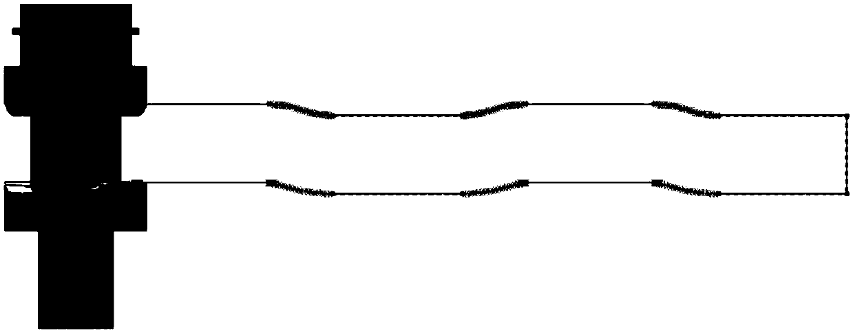

Image

  • Cathode vibration device for electrolytic machining
  • Cathode vibration device for electrolytic machining
  • Cathode vibration device for electrolytic machining

Examples


Embodiment Construction

[0024] The present invention will be described in further detail below in conjunction with the accompanying drawings.

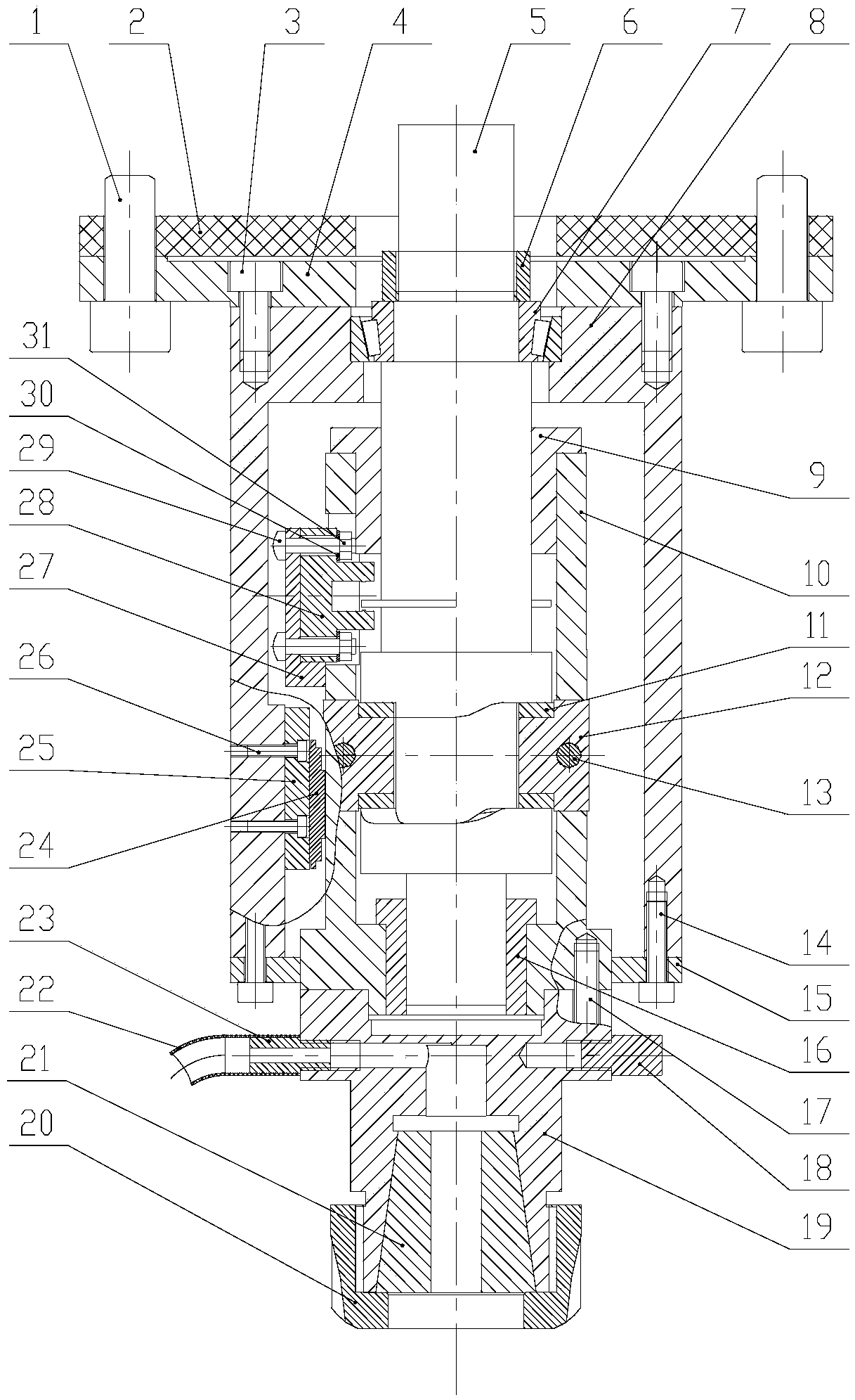
[0025] Such as figure 1 As shown, the electrolytic machining cathode vibration device of the present invention includes: damping screw 1, damping plate 2, first screw 3, connecting flange 4, camshaft 5, lock nut 6, tapered roller bearing 7, guide sleeve 8, Copper sleeve 9, vibration shaft 10, slider 11, slider shaft 12, cylindrical pin 13, second screw 14, guide sleeve cover 15, copper sleeve 16, third screw 17, cathode terminal 18, collet 19, clip Head lock nut 20, spring collet 21, conduit 22, breather pipe 23, MGN slider 24, MGN guide rail 25, fourth screw 26, bracket 27, photoelectric door 28, fifth screw 29, washer 30, nut 31.

[0026] The cathode vibrating device for electrolytic machining of the present invention is installed on the main shaft of the machine tool, wherein the camshaft 5 of the device rotates synchronously with the main shaft of the ma...


PUM


Abstract

The invention discloses a cathode vibration device for electrolytic machining. The cathode vibration device comprises a cam shaft, wherein the cam shaft and a machine tool spindle rotate synchronously, a vibration shaft is arranged on the cam shaft, the end of a rotating shaft is connected with a chuck, a cam groove profile curve is arranged on the cam shaft, sliding blocks which protrude inwardsare arranged on the vibration shaft, the sliding blocks cooperate with the cam groove profile curve, so that the up-down movement of the vibration shaft is realized, and the cam shaft and the vibration shaft are provided with a photoelectric door which is consistent with the up-down movement direction of the vibration shaft. According to the cathode vibration device for electrolytic machining, twopairs of sliding block shafts and the sliding blocks are symmetrically installed, so that the stress of the vibration shaft is symmetrical; and the pulse current and vibration feeding of the cathodevibration device for electrolytic machining are synchronous, when the cathode vibration is fed to the position closest to an anode, a pulse power supply sends pulses, when the cathode vibration is away from the anode, machining gaps start to increase, the dissolution speed of the anode starts to be slowed, an electrolyte can be quickly updated, the pulse power supply does not generate the pulses,thus, stray corrosion can be reduced, energy consumption can be reduced, and the precision of electrolytic machining can be improved.

Description

technical field [0001] The invention relates to a device for synchronizing the turning off and turning on of the high-frequency pulse machining power supply and the vertical vibration of the spindle cathode, mainly used in electrolytic machining. Background technique [0002] Electrolytic machining is a non-contact process, and a certain gap must be maintained between the cathode and the anode during the process. During the machining process, the gap is filled with electrolyte, because all the products dissolved in the electrolytic machining anode are dissolved in the electrolyte, if the electrolyte in the machining gap cannot be updated in time, the electrolytic machining cannot be carried out normally, and even a short circuit will occur in the small gap machining . On the other hand, DC power electrolytic machining will produce stray corrosion, so that electrolytic machining will also occur in parts that do not need to be processed, seriously affecting the machining accu...

Claims


Application Information

Patent Timeline
Patent Type & Authority Applications(China)
IPC IPC(8): B23H3/04B23H11/00
CPCB23H3/04B23H11/00
Inventor 周叙荣干为民蒋永锋夏任波徐波何亚峰黄亮陈阳朱晔
Owner CHANGZHOU INST OF TECH
Learn More