
A method for integrally manufacturing trash rack panels in drainage chambers

A technology of overall production and drainage chambers, which is applied in water conservancy projects, hydroelectric power generation, hydroelectric power stations, etc., and can solve the problems of poor product quality, difficult to reach, and long production cycle.

Active Publication Date: 2020-10-30
SINOHYDRO ENG BUREAU 4 XIANGYUN MACHINERY ENERGY EQUIP CO LTD +1
View PDF8 Cites 0 Cited by
  • Summary
  • Abstract
  • Description
  • Claims
  • Application Information

AI Technical Summary

Problems solved by technology

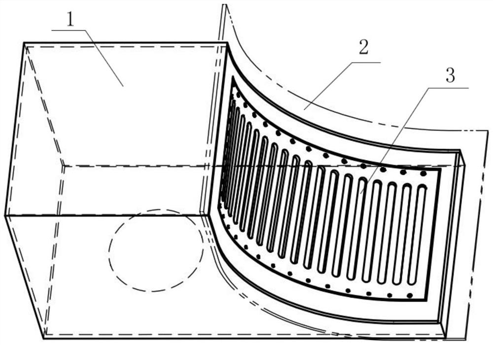
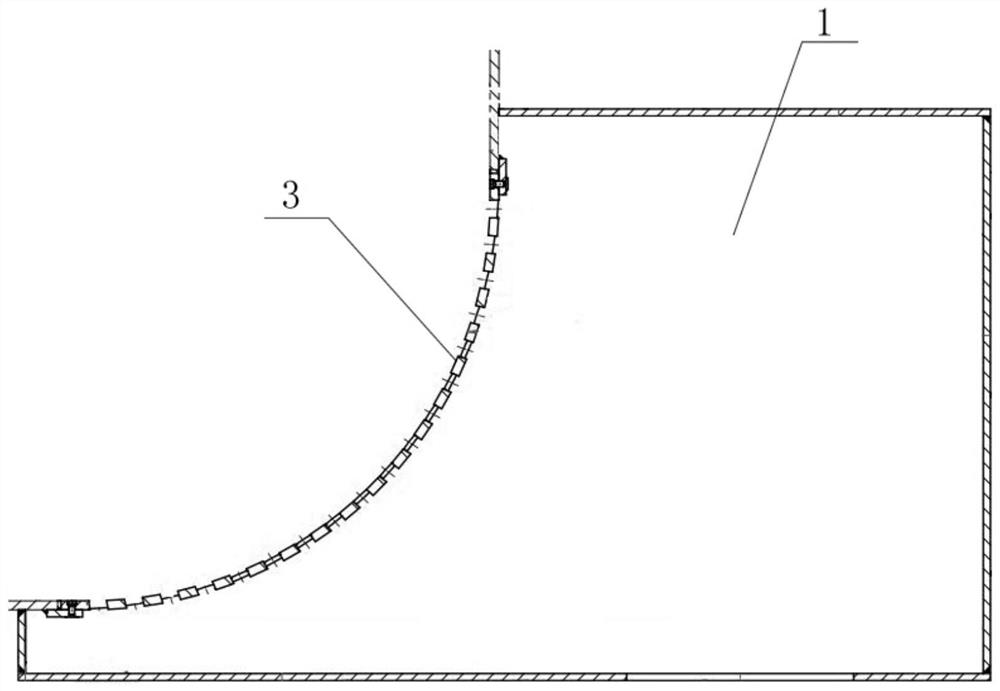
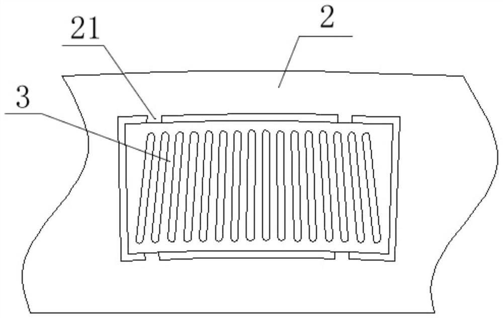
[0002] In the production project of the trash rack plate of the draft pipe drainage chamber of the embedded part of the hydraulic turbine, the trash rack plate needs to be embedded in the tiles, and the trash rack plate is fixed by the outer frame plate and bolts on the outside. The traditional manufacturing method is to separate Roll the trash rack board and tiles, and then assemble the trash rack board to the tiles, but since both the trash rack board and the tiles have radians, it is difficult to achieve the same radian after rolling, and it takes many times Repeat rolling until the radian matches, and when welding the trash rack plate and the tile, the operation is difficult, the existing production method is time-consuming and laborious, the production cycle is long, and the product quality is poor

Method used


Image

  • A method for integrally manufacturing trash rack panels in drainage chambers
  • A method for integrally manufacturing trash rack panels in drainage chambers
  • A method for integrally manufacturing trash rack panels in drainage chambers

Examples


Embodiment 1

[0029] A method for integrally manufacturing a trash rack plate in a drainage chamber, comprising the following steps:

[0030] (1) Measurement and material selection

[0031] Measuring the size of the water outlet of the drainage chamber, selecting tiles, the top and bottom of the tiles have an arc structure, and the size of the tiles is larger than the size of the water outlet of the drainage chamber;

[0032] (2) Determine the opening position

[0033] According to the outlet size of the drainage chamber measured in step (1), determine the reserved position of the trash rack plate on the tile, and the reserved position shall not be at the edge of the tile;

[0034] (3) cutting

[0035] Cut the tile according to the reserved position determined in step (2), and reserve a hole, and leave at least 2 breakpoints on the edge to be bent in the reserved hole during rolling;

[0036] (4) Install the trash rack plate

[0037] Install the trash rack plate into the reserved hole c...


PUM


Abstract

An embodiment of the invention discloses a method of integrally manufacturing a trash rack plate of a drainage chamber. The method comprises the following steps that (1) the size of a water outlet ofthe drainage chamber is measured, a tile with arc-shaped structures on the top edge and the bottom edge is selected, and the size of the tile is larger than that of the water outlet of the drainage chamber; (2) the opening position is determined, specifically, the reserved position of the trash rack plate is determined according to the size of the water outlet of the drainage chamber; (3) cuttingis conducted, specifically, the tile is cut according to the reserved position, a reserved hole is formed, and at least two breakage points are reserved on the edge which needs to be bent and is located in the reserved hole in the rolling process; (4) the trash rack plate is installed, specifically, the trash rack plate is installed in the reserved hole, the trash rack plate and the tile are welded, and the welding positions are the positions of the breakage points; and (5) rolling is conducted, specifically, the tile where the trash rack plate is installed is rolled, so that the trash rack plate of the drainage chamber is obtained. By the adoption of the method, the frequency of rolling of the tile is effectively reduced, and the rolling quality is improved. Meanwhile, the difficulty andthe workload in the process of welding of the trash rack plate and the tile are reduced, the working efficiency is improved, and the cost is saved.

Description

technical field [0001] The invention relates to the technical field of trash rack plate equipment, in particular to a method for integrally manufacturing a trash rack plate in a drainage chamber. Background technique [0002] In the production project of the trash rack plate of the draft pipe drainage chamber of the embedded part of the hydraulic turbine, the trash rack plate needs to be embedded in the tiles, and the trash rack plate is fixed by the outer frame plate and bolts on the outside. The traditional manufacturing method is to separate Roll the trash rack board and tiles, and then assemble the trash rack board to the tiles, but since both the trash rack board and the tiles have radians, it is difficult to achieve the same radian after rolling, and it takes many times Repeat rolling until the radians match, and when welding the trash rack plate and the tiles, the operation is difficult. The existing manufacturing method is time-consuming and laborious, with a long ma...

Claims


Application Information

Patent Timeline
Patent Type & Authority Patents(China)
IPC IPC(8): E02B9/06
CPCE02B9/06Y02E10/20Y02P70/50
Inventor 戚海敏梁金亮廖志文陈文善许文奎李贺威
Owner SINOHYDRO ENG BUREAU 4 XIANGYUN MACHINERY ENERGY EQUIP CO LTD
Learn More