Eureka AIR delivers breakthrough ideas for toughest innovation challenges, trusted by R&D personnel around the world.

An ultrasonic-assisted multi-beam laser fuse additive manufacturing equipment and method

An additive manufacturing and ultrasonic-assisted technology, which is applied in the field of additive manufacturing, can solve problems such as difficult control of the forming quality of laser fuse additives, restrictions on the development of laser fuse additive technology, and reduced sensitivity of the camera system, so as to reduce the overall Effect of heat input, reduction of deformation, and improvement of mechanical properties

Active Publication Date: 2020-11-06
HUAZHONG UNIV OF SCI & TECH
View PDF1 Cites 0 Cited by
  • Summary
  • Abstract
  • Description
  • Claims
  • Application Information

AI Technical Summary

Problems solved by technology

This method ignores the influence of factors such as high temperature environment and molten pool splash on the camera monitoring system during the additive manufacturing process
In addition, due to the small diameter of the wire, the sensitivity of the camera system will be reduced, and it will even be difficult to monitor.
[0005] The above problems make it difficult to control the forming quality of laser fuse additive in the actual application process, and ultimately lead to the inability to effectively complete the entire laser fuse additive manufacturing process within a reasonable time, which seriously restricts the development of laser fuse additive technology

Method used


Image

  • An ultrasonic-assisted multi-beam laser fuse additive manufacturing equipment and method
  • An ultrasonic-assisted multi-beam laser fuse additive manufacturing equipment and method
  • An ultrasonic-assisted multi-beam laser fuse additive manufacturing equipment and method

Examples


Embodiment Construction

[0042] In order to make the object, technical solution and advantages of the present invention clearer, the present invention will be further described in detail below in conjunction with the accompanying drawings and embodiments. It should be understood that the specific embodiments described here are only used to explain the present invention, not to limit the present invention. In addition, the technical features involved in the various embodiments of the present invention described below can be combined with each other as long as they do not constitute a conflict with each other.

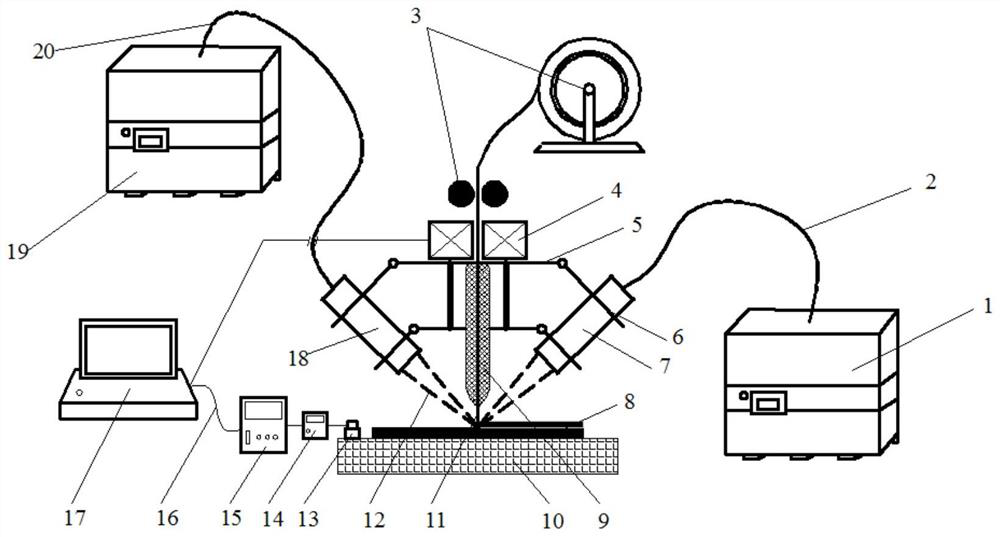
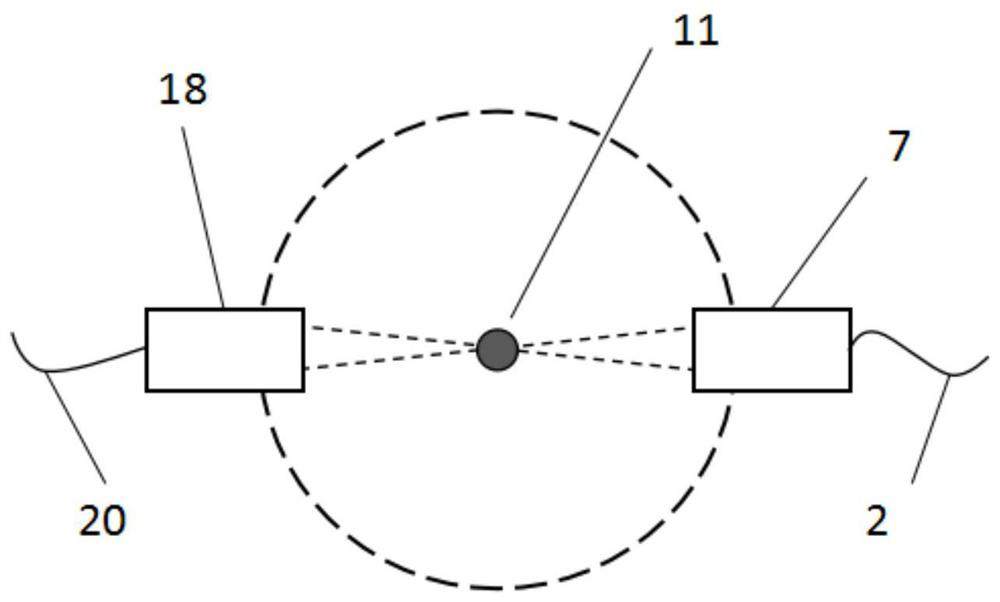
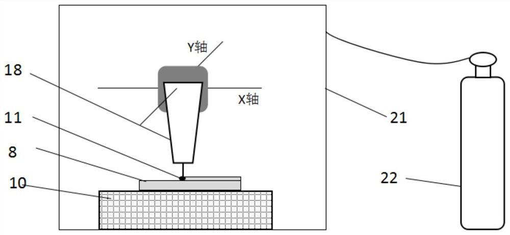
[0043] Such as Figure 1 to Figure 4 As shown, an ultrasonic-assisted multi-beam laser fuse additive manufacturing equipment is characterized in that it includes a laser device, a wire feeding mechanism 3, a substrate 10, a wire guide head 9, an electromagnetic ultrasonic generator 4, and an electromagnetic ultrasonic probe 13 , a controller and a protective gas protection box 21, wherein,

[...


PUM


Abstract

The invention discloses ultrasonic-assisted multi-beam laser wire-melting type additive manufacturing equipment. The equipment comprises a laser device, a wire feeding mechanism, a base plate, a wireguide head, an electromagnetic ultrasonic generator, an electromagnetic ultrasonic probe, a controller and a protective gas protection box, wherein the laser device comprises a laser light source, anoptical fiber and a laser head, the laser light source is connected with the laser head through the optical fiber, the electromagnetic ultrasonic generator is arranged at an inlet of the wire guide head, the electromagnetic ultrasonic probe is arranged on the base plate, and is used for receiving a vibration signal of an accumulated body and transmitting the vibration signal to the controller so that monitoring of a droplet transfer state in the additive manufacturing process can be realized, and the base plate, the wire guide head, the electromagnetic ultrasonic generator and the electromagnetic ultrasonic probe are all located in the protective gas protection box. According to the equipment, the flexibility of the additive manufacturing process can be greatly improved so that the accumulated layers are not prone to collapse, then the mechanical property of the accumulated body can be improved, the deformation can be inhibited, and the speed of the additive process can be increased.

Description

technical field [0001] The invention belongs to the technical field of additive manufacturing, and more particularly relates to an ultrasonic-assisted multi-beam laser fuse additive manufacturing equipment and method. Background technique [0002] Additive manufacturing technology overcomes the large waste of raw materials caused by traditional "material removal" manufacturing, and at the same time has the advantages of rapid prototyping, grain refinement, and uniform organization. It has become the first choice for rapid prototyping technology of complex structural parts. Compared with other metal additive manufacturing technologies, laser fuse additive technology uses high-energy-density laser as the heat source, which has the characteristics of high forming efficiency, and can heat and melt the fed wire according to the predetermined processing path. Layer accumulation, and finally realize the near net shape direct manufacturing of metal parts. This technology is especia...

Claims


Application Information

Patent Timeline
Patent Type & Authority Patents(China)
IPC IPC(8): B23K26/342B23K26/70B23K26/12B23K26/346
CPCB23K26/123B23K26/342B23K26/346B23K26/702
Inventor 庞盛永李权洪胡仁志母中彦梁吕捷罗曼乐兰黄安国
Owner HUAZHONG UNIV OF SCI & TECH
Why Eureka
Eureka Blog
Learn More