
Flue gas treatment device for processing of ores

A technology of flue gas treatment and treatment equipment, which is applied in the field of ore processing, can solve problems such as ineffective treatment, and achieve the effects of avoiding work effects, improving service life, and reducing omissions

Inactive Publication Date: 2019-03-22
李洋洋
View PDF4 Cites 2 Cited by
  • Summary
  • Abstract
  • Description
  • Claims
  • Application Information

AI Technical Summary

Problems solved by technology

However, this equipment has obvious shortcomings. The flue gas produced by ore processing contains sulfide and a large amount of suspended dust, which cannot be effectively treated by a single adsorption device.

Method used


Image

  • Flue gas treatment device for processing of ores
  • Flue gas treatment device for processing of ores
  • Flue gas treatment device for processing of ores

Examples


Embodiment 1

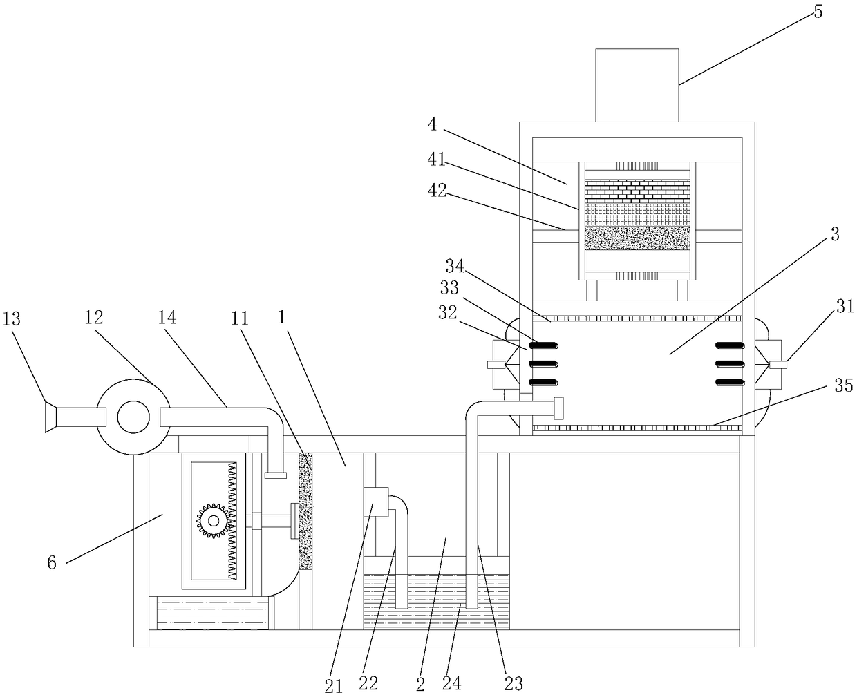
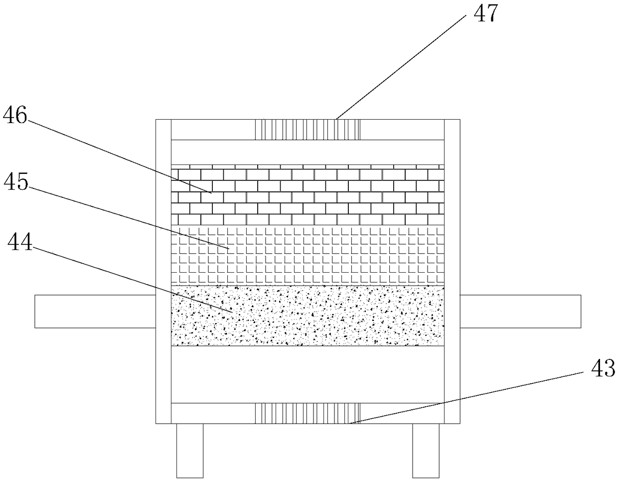
[0025] see figure 1 and figure 2 , a flue gas processing device for ore processing, the processing device is respectively provided with a filter chamber 1, a dedusting and desulfurization chamber 2, an electrostatic dedusting chamber 3, an adsorption processing chamber 4 and a chimney 5, the filter chamber 1 Filter sponge 11 is set, and described filter chamber 1 front end is provided with suction pump 12, and the air intake end of described suction pump 12 is equipped with suction funnel 13, and the air delivery end of suction pump 12 is equipped with air delivery pipe 14, so The bottom end of the air delivery pipe 14 extends into the front side of the filter sponge 11, and the filter sponge 11 performs preliminary filtering treatment on the smoke, and a large amount of dust in the smoke is intercepted and retained in the filter chamber 1.

[0026] The dust removal and desulfurization chamber 2 is located at the rear side of the filter chamber 1, and a drainage pump 21 is a...

Embodiment 2

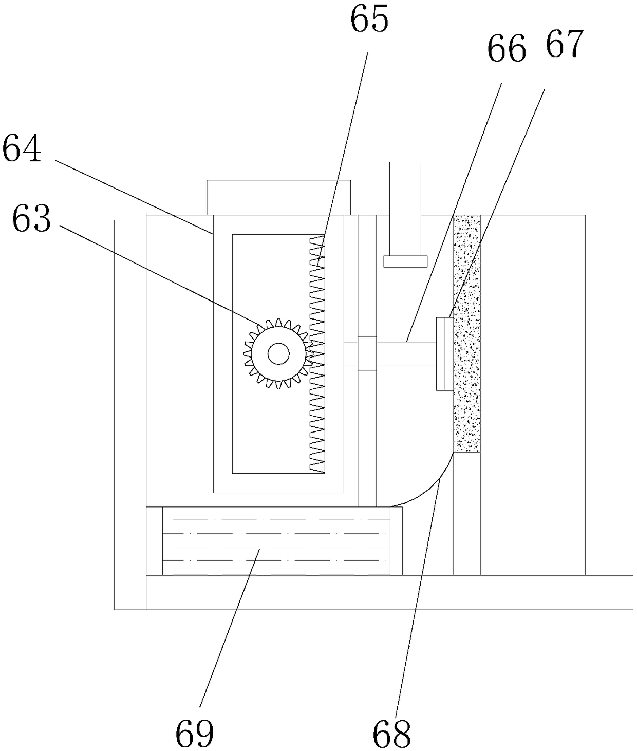
[0033] see image 3 and Figure 4, this embodiment is a further optimization of Embodiment 1. On the basis of it, a dust removal chamber 6 is provided on the front side of the inner chamber of the filter chamber 1, and a movable frame 64 is arranged in the dust removal chamber 6. The dust removal chamber 6 Transmission motor 61 is installed on the side wall of the transmission motor 61, and transmission gear 63 is installed on the driving end of the transmission motor 61 through the driving shaft 62. A rack 65 is provided, the transmission gear 63 is meshed with the rack 65, the rear end of the movable frame 64 is equipped with a fixed rod 66, and a dust wipe 67 is installed on the fixed rod 66, and the dust wipe 67 is connected to the fixed rod 66. The surfaces of the filter sponge 11 are attached to each other, and a diversion slope 68 is arranged under the filter sponge 11 , and a water tank 69 is installed at the end of the diversion slope 68 . A pulley is installed on t...


PUM


Abstract

The invention relates to the field of processing of ores, in particular to a flue gas treatment device for processing of ores. The flue gas treatment device is respectively provided with a filtering cavity, a dedusting and desulfurizing cavity, an electrostatic dedusting cavity, an adsorption cavity and a flue cylinder, wherein the dedusting and desulfurizing cavity is positioned at the back sideof the filtering cavity; a reaction liquid is filled into the dedusting and desulfurizing cavity; the electrostatic dedusting cavity is positioned above the dedusting and desulfurizing cavity; the tail end of an air exhaust guide pipe extends into the electrostatic dedusting cavity; electrodes are respectively arranged at the left side and right side of the electrostatic dedusting cavity; a cathode metal net and an anode metal net are respectively arranged at the upper end and lower end of the electrostatic dedusting cavity, and are electrically connected with the corresponding electrodes. Theflue gas treatment device has the advantage that the suspended particles in the flue gas can be completely removed, so as to ensure the safety in the exhausted air.

Description

technical field [0001] The invention relates to the field of ore processing, in particular to a flue gas treatment device for ore processing. Background technique [0002] With the development of the economy, people's demand for minerals has gradually increased, so the mining industry has also developed rapidly. However, during mining, a large amount of floating smoke and dust will be generated in the air, affecting the quality of the air, polluting the environment, and even affecting the health of workers. The existing air purification equipment cannot meet the needs of air dust removal in mining areas. The effect is not ideal, and a large amount of dust inside the device is not easy to remove, which shortens the service life of the air purification equipment. [0003] Chinese patent (authorized announcement number: CN207412979U) discloses an environmentally friendly quick recovery equipment for mining smoke and dust in the field of mineral engineering. Effect of dust on ...

Claims


Application Information

Patent Timeline
Patent Type & Authority Applications(China)
IPC IPC(8): B01D50/00B01D53/78B01D53/48
CPCB01D50/00B01D53/48B01D53/78B01D2258/0283
Inventor 李洋洋
Owner 李洋洋
Learn More