Eureka AIR delivers breakthrough ideas for toughest innovation challenges, trusted by R&D personnel around the world.

Intelligent cyclic flowing type erosion corrosion testing system and testing method

A technique for scouring corrosion and test systems, which is applied in the direction of testing wear resistance, weather resistance/light resistance/corrosion resistance, measuring devices, etc. It can solve the problem that the concentration, flow rate and temperature of corrosive media cannot be accurately controlled, and the test results cannot truly reflect industrial Actual working conditions, lack of influence of pipe erosion and corrosion characteristics, etc., to achieve the effect of improving safety and efficiency, convenient adjustment in the later stage, and high accuracy

Pending Publication Date: 2019-03-19
ZHEJIANG SCI-TECH UNIV
View PDF0 Cites 5 Cited by
  • Summary
  • Abstract
  • Description
  • Claims
  • Application Information

AI Technical Summary

Problems solved by technology

In the actual industrial production process, there is a lack of scientific experimental test systems and test methods to quantitatively describe the impact of multiphase flow with different medium concentrations, different temperatures, and different flow rates on the erosion and corrosion characteristics of pipes
[0003] The previous research results show that the traditional erosion corrosion test system is mostly rotary, which cannot accurately simulate the erosion corrosion process of the actual industrial pipeline system, and the concentration, flow rate and temperature of the corrosive medium during the experiment cannot be accurately controlled, resulting in the erosion corrosion test. The test results cannot truly reflect the actual industrial conditions

Method used


Image

  • Intelligent cyclic flowing type erosion corrosion testing system and testing method
  • Intelligent cyclic flowing type erosion corrosion testing system and testing method
  • Intelligent cyclic flowing type erosion corrosion testing system and testing method

Examples


Embodiment Construction

[0039]Below in conjunction with accompanying drawing and embodiment the present invention will be further described:

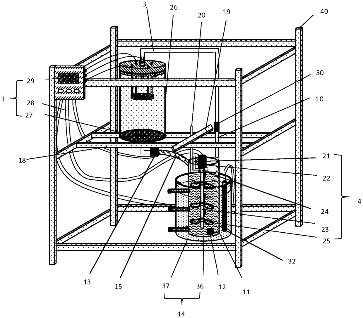
[0040] Such as figure 1 As shown, the present invention includes a frame 40, a temperature control system 1, a test piece erosion corrosion system 2, a test solution circulation system 3 and a test solution stirring system 4; the frame 40 is a cuboid structure, and the middle parts of both sides of the frame are fixed with and the two beams are located at the same height, two first guide rails 18 parallel to each other are slidably installed between the two beams, and the second guide rail 19 is slidably installed on the upper end surfaces of the two first guide rails 18 and perpendicular to the first guide rail 18, The third guide rail 20 is connected to the second guide rail 19 through a corner piece, and the third guide rail 20 is located between the two first guide rails 18 and arranged vertically to the ground.

[0041] The test solution stirring system ...


PUM


Abstract

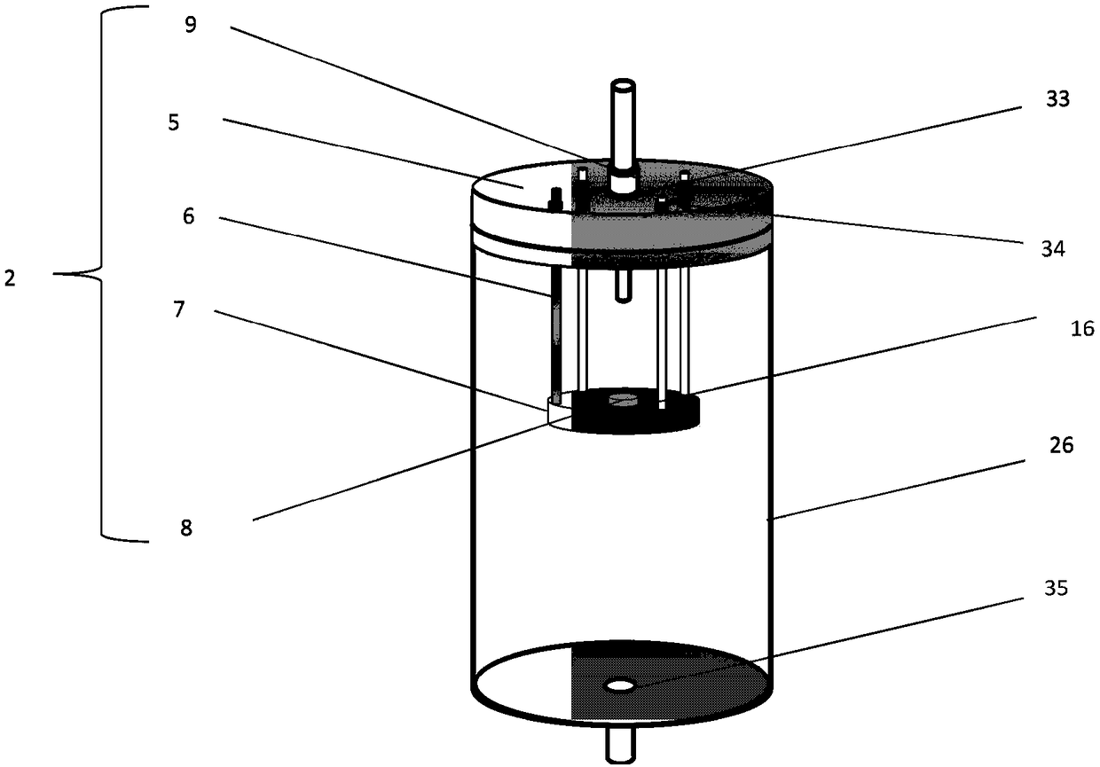
The invention discloses an intelligent cyclic flowing type erosion corrosion testing system and testing method. The system comprises a temperature control system, a test piece erosion corrosion system, a test solution circulating system and a test solution stirring system. The test piece erosion corrosion system comprises a rubber plug, a tower connector, a connecting shaft rod, a test piece platform and a test piece and is mounted between the top and the bottom of a cylindrical test piece tank. One end of a pipeline is connected with the rubber plug while the other end is connected with one end of an upper corrugated pipe, the other end of the upper corrugated pipe is connected with a water pump, and one end of a lower corrugated pipe is connected with the rubber plug while the other endextends into a stirring tank to form the test solution circulating system. A third guide rail is connected with a motor angle part which is connected with a motor, and one end of an extension shaft isconnected with one end of the motor through a coupler while the other end extends into a test solution tank to form the test solution stirring system. The temperature control system comprises three groups of thermocouples, a control circuit and wires. Test piece flushing under different operating conditions is realized, and testing precision is improved.

Description

technical field [0001] The invention belongs to an erosion corrosion test system in the field of flow corrosion protection, and in particular relates to an intelligent circulation flow type erosion corrosion test system and a test method. Background technique [0002] Under the trend of internationalization and globalization of production, safety issues in the continuous industrial production process have increasingly become the focus of all walks of life. In petrochemical, coal chemical, nuclear power industry, ocean engineering and other process industries, multiphase fluids containing corrosive media are highly corrosive to pressure pipes, especially when they contain both corrosive media and solid particles Under the working conditions, it is very easy to cause flow corrosion failure of the pressure pipe and valve system. In the actual industrial production process, there is a lack of scientific experimental testing systems and testing methods to quantitatively describe...

Claims


Application Information

Patent Timeline
Patent Type & Authority Applications(China)
IPC IPC(8): G01N3/56G01N17/00
CPCG01N3/565G01N17/00G01N2203/0005G01N2203/024G01N2203/0242G01N2203/0274G01N2203/0226
Inventor 金浩哲张露滨徐友冰
Owner ZHEJIANG SCI-TECH UNIV
Why Eureka
Eureka Blog
Learn More