Eureka AIR delivers breakthrough ideas for toughest innovation challenges, trusted by R&D personnel around the world.

Prefabricated box beam steel bar framework bundling hydraulic formwork and construction method

A technology of steel skeleton and hydraulic mold, applied in manufacturing tools, ceramic molding machines, building structures, etc., can solve the problems of high labor intensity of operators, difficulty of U-shaped steel skeleton, affecting the accuracy of U-shaped steel skeleton, etc.

Pending Publication Date: 2019-03-19
NINGBO COMM ENG CONSTR GRP
View PDF1 Cites 7 Cited by
  • Summary
  • Abstract
  • Description
  • Claims
  • Application Information

AI Technical Summary

Problems solved by technology

Among these processes, binding the U-shaped steel skeleton requires high precision and strong technical skills, and it is also the most complicated and labor-intensive process.
At present, a fixed steel bottom mold is generally installed at the bottom of the U-shaped steel frame to locate the bottom longitudinal steel bars and floor stirrups. There are three methods for setting the web-shaped steel positioning formwork on both sides of the U-shaped steel frame to locate the web longitudinal steel bars and web stirrups: One is the fixed formwork on both sides, that is, the formwork is set on both sides of the U-shaped steel skeleton. This method has a simple structure, but because the fixed formwork on both sides of the U-shaped steel Due to the existence of frictional resistance, it is difficult to lift out the U-shaped steel frame as a whole, so a certain gap must be left between the fixed formwork on both sides and the longitudinal steel bars and web steel bars, which affects the accuracy of the U-shaped steel frame; The second is the movable formwork on both sides, that is, the movable formwork is set on both sides of the U-shaped steel skeleton. The longitudinal reinforcement of the web and the web stirrup are fixed and bound and then removed from the formwork on both sides. Manual movement is time-consuming and laborious. The labor intensity is high; the third is the fixed and movable formwork on both sides, the published utility model patent CN201420061840.4 "a prefabricated small box girder steel skeleton tire formwork for expressways", that is, a support with a large number of rotating side belly reinforcements The rod separates the positioning chuck from the steel frame, and separates the steel frame as a whole from the formwork on both sides. This method also has the disadvantage of time-consuming and laborious

Method used


Image

  • Prefabricated box beam steel bar framework bundling hydraulic formwork and construction method
  • Prefabricated box beam steel bar framework bundling hydraulic formwork and construction method
  • Prefabricated box beam steel bar framework bundling hydraulic formwork and construction method

Examples


Embodiment Construction

[0074] The embodiments of the present invention will be described in detail below according to the above-mentioned drawings.

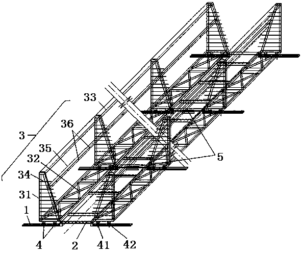
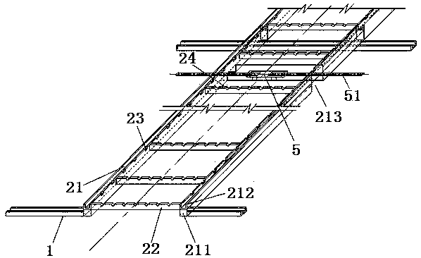
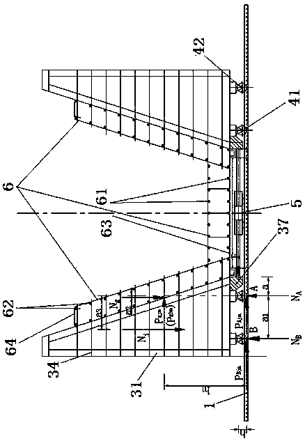
[0075] Such as Figure 1~Figure 3 As shown, 1. Track, 2. Fixed base, 21. Longitudinal beam, 211. Longitudinal beam square steel, 212. Longitudinal beam channel steel, 22. Cross beam, 23. Longitudinal beam positioning slot, 24. Cross beam positioning slot, 3. Mobile frame , 31. Vertical frame, 32. Underframe, 33. Top corrugation, 34. Secondary rib positioning rod, 35. Vertical stirrup positioning rod, 36. Vertical stirrup positioning groove, 37. Bracket, 4. Moving wheel, 41 . Moving wheel A, 42. Moving wheel B, 5. Hydraulic system, 51. Hydraulic rod, 6. Steel frame, 61. Main reinforcement, 62. Secondary reinforcement, 63. Flat stirrup, 64. Vertical stirrup.

[0076] A hydraulic formwork and construction method for binding prefabricated box girder reinforcing steel frame, such as figure 1 As shown, it mainly relates to the field of bridge construction.

[007...


PUM


Abstract

The invention discloses a prefabricated box beam steel bar framework bundling hydraulic formwork and a construction method, and belongs to the field of bridge construction. The prefabricated box beamsteel bar framework bundling hydraulic formwork structurally comprises tracks, moving frames, a steel bar framework and the like. Mainly, combined design is adopted in the two moving frames and a fixing base. A plurality of hydraulic systems are used for synchronously driving the two moving frames to oppositely move and be gathered so that the steel bar framework can be positioned for bundling forming, or to move, separate from each other and disengage from the steel bar framework, and hoisting-out is convenient. The structure has the advantages that firstly, the structure is simple, usage isconvenient, and the labor intensity of operation personnel is relieved; secondly, the steel bar framework manufacturing precision is high, errors are few, the thickness of a box beam concrete protection layer is better guaranteed, and durability is improved; and thirdly, through the hydraulic systems, the mechanical degree of the formwork is improved, construction is rapid, and the production efficiency is high. Thus, the prefabricated box beam steel bar framework bundling hydraulic formwork is designed, the corresponding construction method is combined, so that the advantages that the integral construction quality is improved, the durability of the engineering structure is enhanced, and energy saving and emission reducing are achieved are achieved, and economic benefits and social benefits are obvious.

Description

Technical field [0001] The invention relates to the field of bridge construction, in particular to a hydraulic formwork for binding a prefabricated box girder steel bar skeleton and a construction method. Background technique [0002] The prefabricated box girder usually separates the U-shaped steel framework and the roof steel framework below the top slab and binds them to form, and then hoists the U-shaped steel framework into the prefabricated outer formwork as a whole, then places the inner mold, installs the roof steel framework, and pours the concrete. Among these processes, tying the U-shaped steel bar framework requires high precision, strong technicality, and is also the most complicated and labor-intensive process. Currently, a fixed steel bottom mold is generally installed at the bottom of the U-shaped reinforcing steel frame to locate the bottom longitudinal steel bars and bottom plate stirrups. There are three methods for installing web-shaped steel positioning molds...

Claims


Application Information

Patent Timeline
IPC IPC(8): B28B23/04E04G21/12
CPCE04G21/12B28B23/04
Inventor 吴江张友全徐宏海申洛岑曹超云曹连聪徐建东黄剑云傅健云肖天翔段群苗周一勤
Owner NINGBO COMM ENG CONSTR GRP
Why Eureka
Eureka Blog
Learn More