High-power pulse generator and high-power pulse power supply

A high-power pulse and pulse generator technology, applied in the field of high-power pulse generators to generate high-power pulses, can solve problems such as fire, current imbalance, local switch tube overcurrent damage, etc., to prevent fires and reduce low energy efficiency. problem, the effect of suppressing current unevenness in solid-state switches

Pending Publication Date: 2019-03-15
FUDAN UNIV
View PDF0 Cites 5 Cited by
  • Summary
  • Abstract
  • Description
  • Claims
  • Application Information

AI Technical Summary

Problems solved by technology

[0006] The solid-state Marx pulse voltage superimposer is limited by the maximum current capacity of a single solid-state switch, and it has always been unable to greatly increase its output current
However, simply using solid-state Marx pulse voltage superimposers in parallel will easily lead to unbalanced output current of each pulse voltage superimposer, and local switching tubes are prone to overcurrent damage, which will cause fires, explosions and other problems, posing a great safety hazard
[0007] The solid-state LTD pulse current source is limited by the saturation problem of the magnetic core, and cannot output pulse waveforms with long pulse widths
In addition, since the solid-state LTD pulse current source uses a magnetic core directly at the power end of the power supply for energy coupling, the loss of the magnetic core is very serious, and the energy efficiency is generally low. At the same time, an external reset circuit is required to avoid saturation of the magnetic core.

Method used


Image

  • High-power pulse generator and high-power pulse power supply
  • High-power pulse generator and high-power pulse power supply
  • High-power pulse generator and high-power pulse power supply

Examples


Embodiment Construction

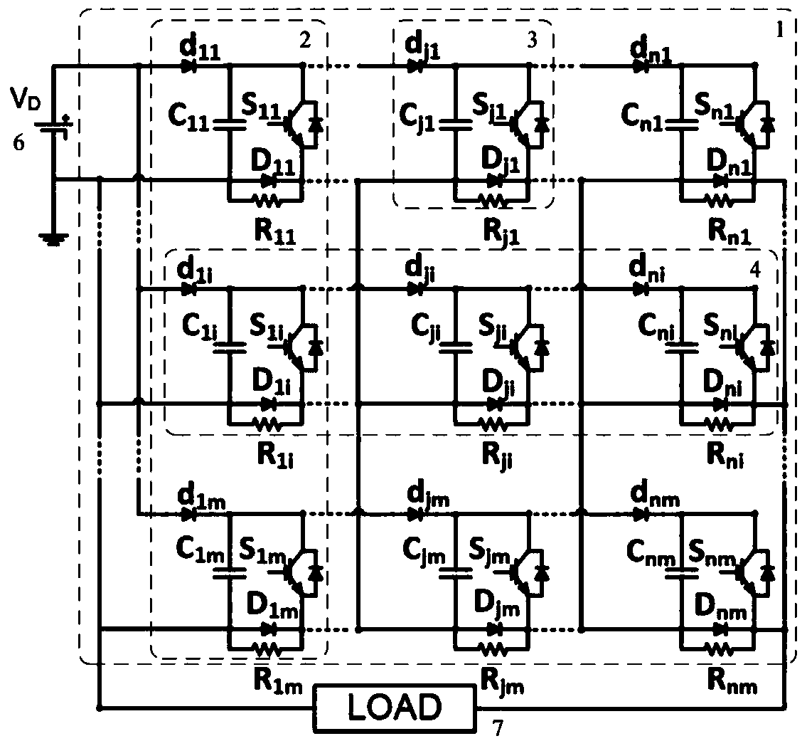
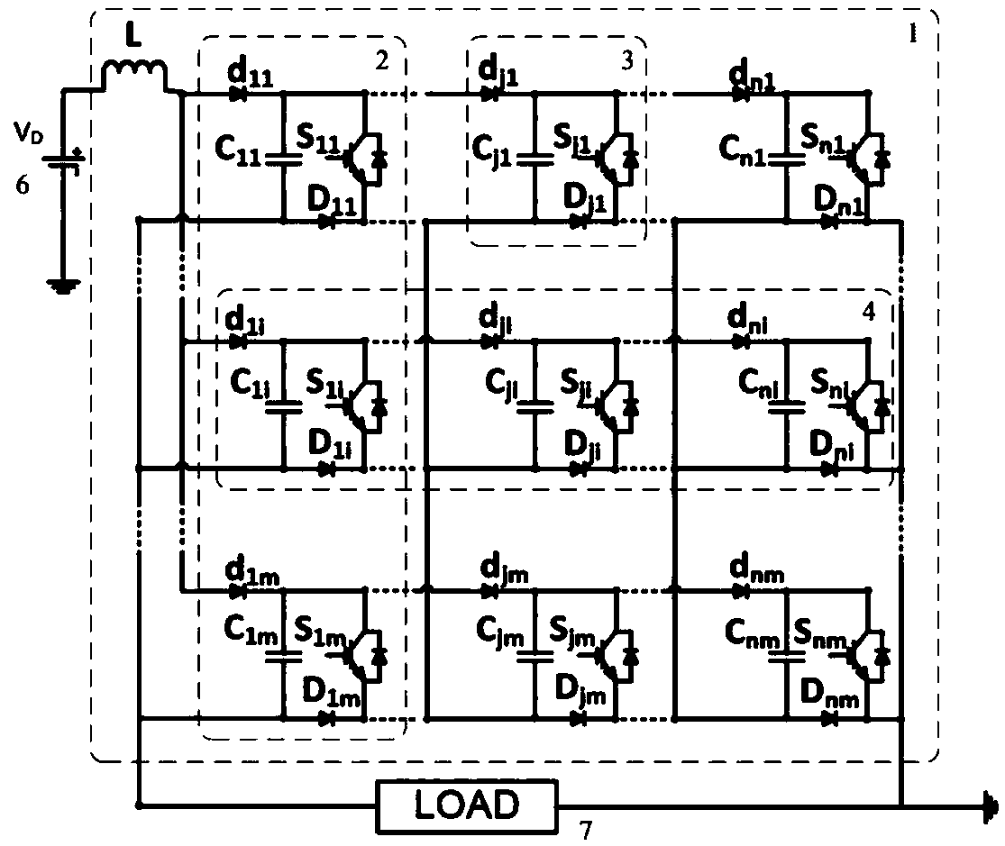
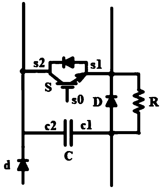
[0102] The implementation of the present invention will be illustrated by specific specific examples below, and those skilled in the art can easily understand other advantages and effects of the present invention from the content disclosed in this specification. Although the description of the invention will be presented in conjunction with a preferred embodiment, it is not intended that the features of the invention be limited to that embodiment only. On the contrary, the purpose of introducing the invention in conjunction with the embodiments is to cover other options or modifications that may be extended based on the claims of the present invention. The following description contains numerous specific details in order to provide a thorough understanding of the present invention. The invention may also be practiced without these details. Also, some specific details will be omitted from the description in order to avoid obscuring or obscuring the gist of the present inventio...


PUM


Abstract

The invention belongs to the technical field of high-power pulses, and particularly discloses a high-power pulse generator, a high-power pulse power supply and a high-power pulse generation method. The pulse generator comprises a main body composed of multiple stages of pulse modules connected stage by stage; and each pulse module generate an output waveform in response to a driving signal. Each pulse module comprises an energy storage capacitor with a first end and a second end, a plurality of equipotential solid-state switches, first isolation devices and second isolation devices, wherein each solid-state switch comprises a driving end, a first power end and a second power end, and the second power end is connected with the second end of the energy storage capacitor; the first isolationdevices are connected between the first end of the energy storage capacitor and the first power ends of the solid-state switches in series; and the second isolation devices are connected between the second end of the energy storage capacitor of the pulse module and the second power ends of the solid-state switches of the adjacent stage of the pulse module in series. The pulse generator has the beneficial effects that a high-power pulse output with a high voltage, a high current, a fast edge and a wide pulse can be generated.

Description

technical field [0001] The invention relates to the field of high-power pulse power supplies, in particular to a high-power pulse generator, a high-power pulse power supply, and a method for generating high-power pulses. Background technique [0002] High-power pulsed power supplies are widely used in military industrial fields such as plasma technology, nuclear physics technology, strong laser technology, high-energy particle acceleration technology and electromagnetic pulse technology. [0003] In recent years, high-power pulse power supply has gradually been used in sewage degradation and flue gas desulfurization and denitrification in the field of environmental protection; human cell tissue treatment in the field of biomedicine; surface modification of materials in the field of materials and precision processing; and food preservation and sterilization in the field of food processing Used in civilian fields such as disinfection. [0004] Traditional high-power pulse pow...

Claims


Application Information

Patent Timeline
IPC IPC(8): H03K4/06H03K3/017H03K5/04H02J7/00H02J7/34
CPCH03K4/063H02J7/0068H02J7/345H03K3/017H03K5/04
Inventor 刘克富邱剑王亦凡
Owner FUDAN UNIV
Why Eureka
Try Eureka