
Biomass rotary fire grate combustor

A technology of rotary grate and biomass, applied in the combustion method, combustion equipment, combustion of solid fuel, etc., can solve the problems of inability to work at the same time, incomplete combustion, rising exhaust gas temperature, etc., to expand compatibility and stability , The fuel combustion process is sufficient, and the effect of improving the combustion efficiency

Pending Publication Date: 2019-03-08
辛集市卓伟生物质压块燃烧机有限公司
View PDF0 Cites 5 Cited by
  • Summary
  • Abstract
  • Description
  • Claims
  • Application Information

AI Technical Summary

Problems solved by technology

[0003] There are many types of biomass fuels available, and the fuels have the characteristics of high water content (generally above 45%), many impurities (mixed with soil and fine sand), high ash content, and high alkali metal content. At present, the fuel of the burner is mainly It is biomass particles, which are not suitable for fuels such as biomass briquettes, shavings, rice husks, corncobs, etc. When such fuels are directly accumulated in the furnace, due to the unreasonable structure of the furnace, after the fuel in the furnace is burned, the furnace will If the internal heat distribution is uneven, the ash in the high temperature zone will coke in the low temperature zone after softening
Coking in the boiler will reduce the combustion efficiency of normal fuel, block the furnace, change the heat distribution in the furnace, further aggravate the coking tendency, reduce the steam temperature of the boiler, increase the exhaust gas temperature, and produce a large amount of harmful substances such as exhaust gas and smoke. This will intensify slagging, coking, and increase the possibility of deflagration, so that the burned biomass ash cannot be cleaned easily, quickly, and continuously, resulting in the inability of the burner to continue to work, thereby failing to meet the requirements of normal production
[0004] At present, there are two main methods for dealing with slagging and coking of biomass burners: one is to use steam soot blower to carry out coking and ash removal on the heating surface, because the content of potassium in biomass fuel is relatively high, and the potassium-containing ash is attached The focus is very strong, it is difficult to clean up the coke blocks, and there is also a method of using decoking inhibitors. Another method is to add inhibitors to the fuel, which increases the production cost, and is not conducive to environmental protection, which violates the use of biomass fuels. original intention
Although the above two methods have alleviated the slagging and coking phenomena to a certain extent, they have not fundamentally solved the problems of incomplete combustion, high combustion costs, toxic substances and smoke emissions due to incomplete combustion, and environmental pollution.
[0005] At present, there are mainly two methods for biomass burners to deal with biomass ash: one is to use manual slag and ash removal methods, and manually use slag and ash removal tools to remove slag and ash, but manual slag and ash removal is not cleaned thoroughly, Low efficiency, dangerous operation and other problems, another kind of external slag and dust removal machine is used for slag and ash removal, but the external slag and dust removal machine needs to be connected to the burner with an external delivery pipeline, which is time-consuming and laborious. And there are problems such as incomplete slag and dust removal, inability to work at the same time, slow efficiency, etc.

Method used


Image

  • Biomass rotary fire grate combustor
  • Biomass rotary fire grate combustor
  • Biomass rotary fire grate combustor

Examples


Embodiment

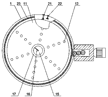
[0026] The invention provides a biomass rotary grate burner, which consists of a furnace body 1, a water interlayer 2, a refractory pouring layer 3, a furnace 4, an air distribution port 5, a flame nozzle 6, an air distribution pipe 7, a driving gear 8, and a driving motor 9. Furnace body base 10, rotating grate 11, wind cap 12, water-sealed air cavity 13, inner ash removal piece 14, installation shaft 15, screw auger 16, ash drop port 17, air inlet sleeve 18, outer ash removal piece 19. Positioning ring 20, positioning support 21, bottom support 22, gear ring 23, secondary blower 24, primary blower 25, auger drive shaft 26, spiral reamer 27, rotating auger 28, vibration rod 29, feed bin 30, slag collection tank 31, built-in air distributor 32, secondary spiral air duct 33, drive rod 34, stirring rod 35, conveyor belt 36, slag discharge plate 37, drive wheel 38, and is set in the furnace body 1 to rotate The grate device and the three-dimensional slag removal mechanism are loc...


PUM


Abstract

The invention relates to a biomass combustor, in particular to a biomass rotary fire grate combustor which is suitable for mass biomass fuel and capable of preventing slag bonding and coking. The biomass rotary fire grate combustor comprises a furnace body, a rotary fire grate device arranged in the furnace body, a three-dimensional slag cleaning mechanism arranged in the furnace body, and a furnace body base located at the lower part of the furnace body, wherein a wind inlet device is arranged on the furnace body base; a feeding device is arranged above the wind inlet device; the wind inlet device communicates with the furnace body base and a flaming mouth of the furnace body; and the feeding device is connected with a feeding opening of the furnace body. According to the biomass rotary fire grate combustor disclosed by the invention, an auxiliary rotary slag cleaning machine is arranged at an ash falling opening of the furnace body and the rotary fire grate device, so that firstly, fuel accumulated on the rotary fire grate is sufficiently stirred; then the fuel is sufficiently combusted, bonded slags and cokes which are not sufficiently combusted on the rotary fire grate can be effectively crushed, and are transported to an ash outlet groove through a rotary auger arranged on the auxiliary rotary slag cleaning machine, so that the situation that the ash falling opening is blocked by the too much bonded slags and the too much cokes is avoided.

Description

technical field [0001] The invention relates to a biomass burner, in particular to a biomass rotary grate burner suitable for multi-biomass fuels and preventing slagging and coking. Background technique [0002] Biomass fuel is a new type of clean fuel that uses agricultural and forestry waste as a raw material and is made into various shapes (such as lumps, granules, etc.) through crushing, mixing, extrusion, drying, etc., and can be directly burned. fuel. [0003] There are many types of biomass fuels available, and the fuels have the characteristics of high water content (generally above 45%), many impurities (mixed with soil and fine sand), high ash content, and high alkali metal content. At present, the fuel of the burner is mainly It is biomass particles, which are not suitable for fuels such as biomass briquettes, shavings, rice husks, corncobs, etc. When such fuels are directly accumulated in the furnace, due to the unreasonable structure of the furnace, after the f...

Claims


Application Information

Patent Timeline
IPC IPC(8): F23B30/04F23J1/02F23L1/02F23L9/00
CPCF23B30/04F23J1/02F23L1/02F23L9/00
Inventor 刘超
Owner 辛集市卓伟生物质压块燃烧机有限公司
Learn More