Permeable base layer and construction method thereof

A technology of permeable base and permeable layer, which is applied in the direction of roads, side ditch/curb, coagulation pavement laid on site, etc. The effect of increasing the rate, increasing the need for immediate drainage

Pending Publication Date: 2019-03-08
成都建工第三建筑工程有限公司
View PDF9 Cites 0 Cited by
  • Summary
  • Abstract
  • Description
  • Claims
  • Application Information

AI Technical Summary

Problems solved by technology

[0003] The purpose of this application is to provide a permeable base and its construction method to solve the problem that the water permeability and structural strength of the base cannot be balanced in the prior art

Method used


Image

  • Permeable base layer and construction method thereof
  • Permeable base layer and construction method thereof
  • Permeable base layer and construction method thereof

Examples


Embodiment 1

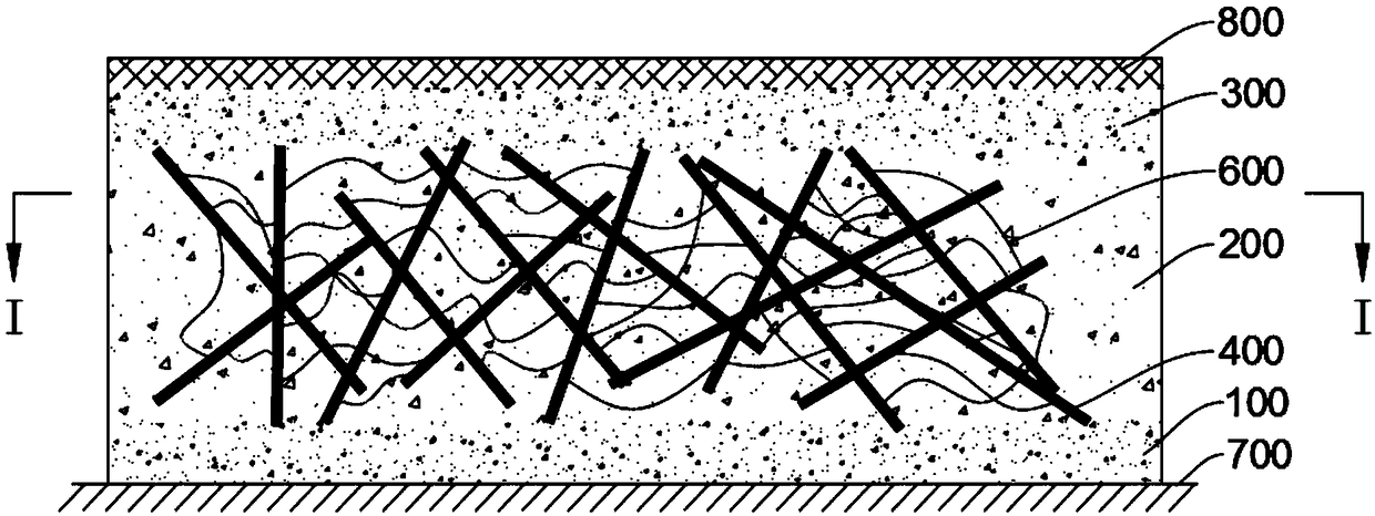
[0031] This embodiment provides a permeable base layer, which is arranged between the roadbed 700 of the permeable pavement 800 and the road surface 800, and is used to solve the problem of high porosity of the base layer and low structural strength when the water permeability is good. Water permeability and higher structural strength, when the water permeability is good, it can also have a better load-bearing capacity, and it is not prone to adverse conditions such as settlement and depression.

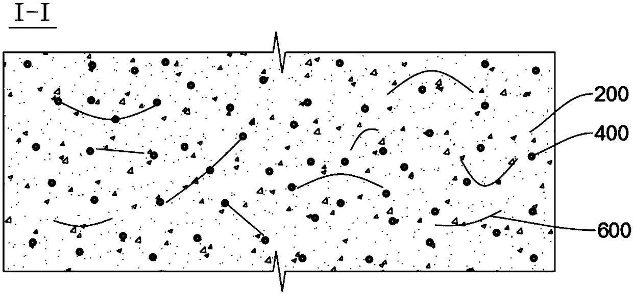
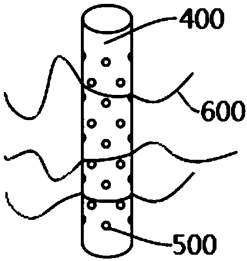
[0032] Attached figure 1 It is a schematic diagram of the cross-sectional structure of the permeable base of the road provided in this embodiment; figure 2 Yes figure 1 Section I-I taken from the stabilization layer 200 in the middle; attached image 3 It is a schematic diagram of the structure of the pipe body 400 provided in the stabilizing layer 200.

[0033] Please refer to the attached figure 1 As shown, the direction from the roadbed 700 to the road surface 800 of the above-mentione...

Embodiment 2

[0061] This embodiment provides a construction method for a permeable base layer, which includes the following steps.

[0062] Laying the first permeable layer 100: laying a gravel concrete layer on the roadbed 700, optionally making the first permeable layer 100 and the roadbed 700 approximately the same width, or optionally making the first permeable layer 100 slightly narrower than the first permeable layer 100, And level it.

[0063] In this embodiment, the width of the first water-permeable layer 100 is 4 m.

[0064] Set the stability layer 200:

[0065] Fixed tube 400

[0066] Before the first water-permeable layer 100 is solidified and formed, a plurality of pipe bodies 400 are obliquely inserted into the first water-permeable layer 100 at a predetermined angle greater than 0° and less than 180° to fix them, and fix the crossing parts of the pipe bodies 400, for example It is fixed by AB glue bonding, or welding, or tying, and the specific fixing method shall be subject to firm...


PUM


Abstract

The invention relates to the field of permeable base layers, specifically relates to a permeable base layer and a construction method thereof and aims at solving the problem that permeable capacity and structural strength of a base layer in the prior art cannot be taken into consideration together. The permeable base layer comprises a permeable stable layer, wherein the stable layer is prepared from filler and a plurality of pipe bodies; each pipe body at least comprises a runner in the axial direction, the runner is used for allowing water flow to pass through, and the runner at least penetrates through the end of each pipe body; all the pipe bodies are fixedly arranged according to a preset angle at the road surface, and the preset angle is larger than 0 degree and smaller than 180 degrees; the plurality of the pipe bodies mutually cross to form a net shape, the filler is filled into gaps of the net-shape structure formed by the pipe bodies, the pipe bodies are mutually connected orsupported by the filler to keep the preset angles of all the pipe bodies. The pipe bodies form the net-shaped structure, so that structural strength, rigidity and deformation resistance of the stablelayer can be enhanced, and permeable capacity and structural strength of the stable layer are both taken into consideration; meanwhile, hollow structures of the pipe bodies further can improve temporary water holding capacity of the stable layer, so that the instant water draining speed of the road surface is further improved.

Description

Technical field [0001] This application relates to the field of permeable bases, and specifically to a permeable base and a construction method thereof. Background technique [0002] In order to alleviate the negative impact of hardened pavement on water resources and alleviate the impact of hardened pavement on municipal drainage, permeable bases are often installed on hardened pavements. The water permeability of existing permeable bases is mainly controlled by the porosity of the laid filler When the porosity of the filler is larger, the water permeability of the permeable base layer is stronger, and when the porosity of the filler is smaller, the water permeability of the water permeable base layer is weaker. The porosity of the filler is also related to the strength of the permeable base layer. The greater the porosity of the filler, the lower the strength of the permeable base layer. The permeable base layer is more prone to settlements and depressions. Summary of the inve...

Claims


Application Information

Patent Timeline
Patent Type & Authority Applications(China)
IPC IPC(8): E01C7/00E01C11/22
CPCE01C7/00E01C11/22
Inventor 夏葵胡刚侯正国黄尚珩李杰吴思聪凌书刘启超杨德志文兴成
Owner 成都建工第三建筑工程有限公司
Why Eureka
Try Eureka