Lamination method and lamination device for film display and flexible circuit board

A flexible circuit board and pressing device technology, applied in identification devices, printed circuits, printed circuits, etc., can solve the problems of warping of substrates due to heat, increase of product defect rate, deviation of alignment accuracy, etc.

Inactive Publication Date: 2020-08-14
USUN TECH CO LTD
View PDF13 Cites 0 Cited by
  • Summary
  • Abstract
  • Description
  • Claims
  • Application Information

AI Technical Summary

Problems solved by technology

[0004] In addition, the thin film display A may use plastic materials (such as various films such as PI, PET, or PE) as the upper and lower substrates, and when the thin film display A and the flexible circuit board C are subjected to thermal compression processing, it may cause the plastic on the , Warpage and arc bending of the lower substrate due to heat, which affect the deviation of the alignment accuracy when the transmission interface A1 and the connection interface C1 are pressed together, resulting in an increase in the defective rate of the product. In the actual operation process, there are many deficiencies
[0005] Therefore, how to solve the problems and troubles that the different thermal expansion ratios between different materials affect the transmission interface and the size change of the connection interface when the thin film display and the flexible circuit board are processed by heat compression, and it is easy to cause the thin film display and the flexible circuit board. When the plastic substrate is thermally deformed and affects the thermocompression operation, the lack and troubles of the alignment accuracy deviation of the transmission interface and the connection interface, etc., are the directions that relevant manufacturers engaged in this industry are eager to study and improve.

Method used


Image

  • Lamination method and lamination device for film display and flexible circuit board
  • Lamination method and lamination device for film display and flexible circuit board
  • Lamination method and lamination device for film display and flexible circuit board

Examples


Embodiment Construction

[0019] In order to achieve the above-mentioned purpose and effect, the technical means adopted in the present invention, its structure, and the method of implementation, etc., are hereby described in detail with respect to the preferred embodiments of the present invention. Its features and functions are as follows, in order to fully understand.

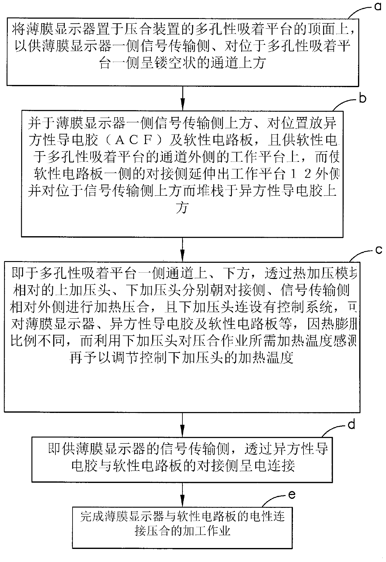
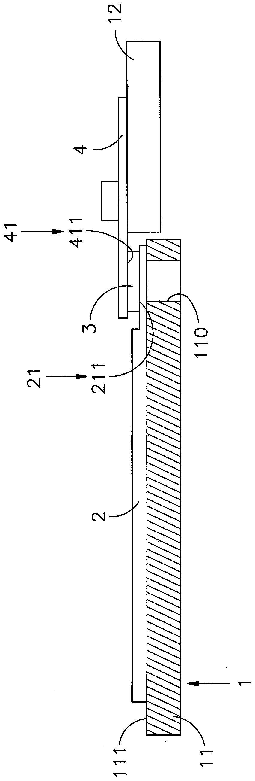
[0020] see Figure 1-5 As shown, it is a flow chart, a side view, a side sectional view, a side view before the processing of the hot pressing module, and a side view after the processing of the hot pressing module of the pressing method of the present invention. It can be clearly seen from the figure , the lamination method of thin film display and flexible circuit board of the present invention comprises lamination device 1, thin film display 2, anisotropic conductive adhesive 3, flexible circuit board 4 and thermal pressurization module 5, wherein, heat The pressing steps are:

[0021] (a) Place the thin film display 2 on the top...


PUM


Abstract

The invention relates to a lamination method and lamination device of a thin film display and a flexible circuit board. The porous adsorption platform of the lamination device is provided with a hollow channel on one side, and the top absorbs the thin film display through the adsorption plane, and The outer side of the porous adsorption platform of the adjacent channel is provided with a working platform for placing the flexible circuit board, so that the docking side of the flexible circuit board extends to the top of the signal transmission side on the side of the film display, and then on the signal transmission side, docking The anisotropic conductive adhesive is set between the sides, that is, the upper and lower pressure heads of the thermal pressurization module on the upper and lower channels of the adsorption platform are respectively held against the docking side and the anisotropy on the signal transmission side by using porosity. The conductive adhesive is heated and pressed to achieve the purpose of adjusting the upper pressure head and the lower pressure head to perform heat and pressure at the same or different temperatures.

Description

technical field [0001] The invention provides a lamination method and a lamination device of a film display and a flexible circuit board, especially a lamination device and a lamination method capable of adjusting the heat lamination temperature of a heating and pressurizing module, for the film display The signal transmission side and the docking side of the flexible circuit board are accurately aligned and electrically combined to achieve the purpose of accelerating the thermocompression operation. Background technique [0002] Screens such as picture tube TVs or cathode ray tube monitors (Cathode raytube) that are traditionally used to display video and audio signals, because traditional screens are large and heavy, it is quite inconvenient to carry or install and apply. With the continuous advancement of technology , audio-visual displays have been developing towards thinner, flatter, and lighter weight. Various liquid crystal displays, light-emitting diode displays, or ...

Claims


Application Information

Patent Timeline
Patent Type & Authority Patents(China)
IPC IPC(8): H05K3/32G09F9/30
CPCG09F9/301H05K3/321H05K2201/10128H05K2203/0278G09F27/00
Inventor 黄文全黄秋逢
Owner USUN TECH CO LTD
Why Eureka
Try Eureka