Backrest-seat synchronous linkage device for office chair
A technology of synchronous linkage and office chairs, which is applied in the field of swivel chairs and office chairs, can solve the problem of fewer parts and achieve the effect of simple structure and not easy to rub the back
- Summary
- Abstract
- Description
- Claims
- Application Information
AI Technical Summary
Problems solved by technology
Method used
Image
Examples
Embodiment 1
[0073] Embodiment 1: first define the reference orientation of each part of the present invention, the present invention is when office chair is installed normally, and the front of office chair is front end, front part, and the rear of office chair comprises the position of chair back, seesaw where is Rear end, rear.
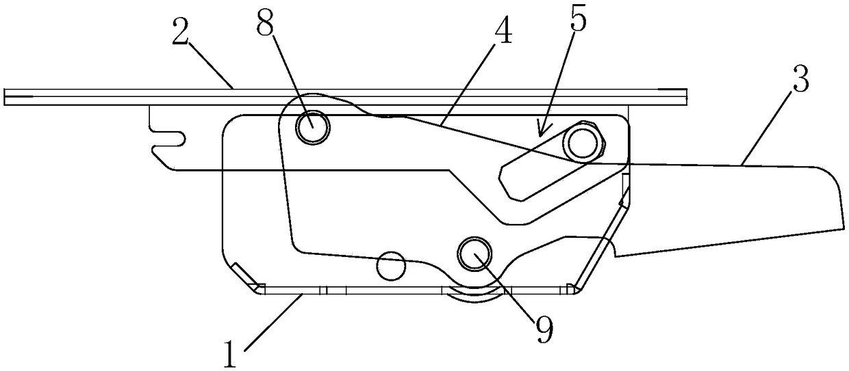
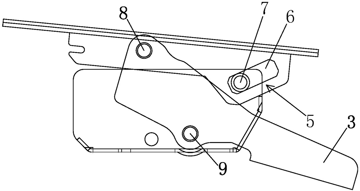
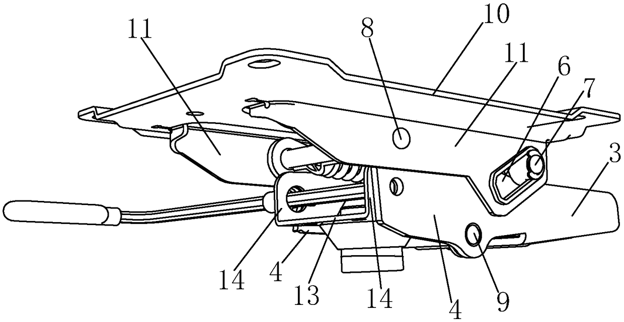
[0074] The synchronous linkage device for the back seat of the office chair of the present embodiment, such as Figure 1 to Figure 14 As shown, it includes a base 1, a bracket 2 for connecting the seat, a seesaw 3 for connecting the back of the chair, and at least one crank 4. The upper and lower ends of the crank 4 are respectively hinged with the front of the bracket 2 and the base 1. The crank 4 is arranged obliquely, and the seesaw 3 and the crank 4 are connected as a whole. It can also be said that the seesaw 3 and the crank 4 are integrally formed; The chute guide mechanism 5 for lifting guidance; when the seesaw 3 rotates to a larger or smaller inclinat...
Embodiment 2
[0082] Example 2: Figure 15 , 16 A base structure of the device of the present invention is illustrated, the base 1 includes a base plate 13 and side plates 14 extending upward along both sides of the base plate 13, the hinge point 41 between the lower end of the crank 4 and the base 1 is at the lower end of the side plate 14, for To meet the inclination of the crank, the height of the side plate 14 is more than 8CM; and the sleeve 44 for inserting the support rod is arranged in the base, and is reinforced by the cuboid reinforcement seat 47 surrounding the sleeve 44 in the base, but This may make the height and weight of the main body of the base 1 too large, which is not conducive to the development towards the direction of weight reduction.
[0083] Figure 17 , 18 An improved base structure is shown. The base 1 also includes a base plate 13 and side plates 14 extending upward along both sides of the base plate 13. The overall height of the side plates 14 is 3.5-4.5 cm....
Embodiment 3
[0086] Embodiment 3: as Figure 21 , 22 As shown, in this embodiment, no connection plate is provided on the bottom surface of the base 1, and the lug 43 is integrally formed with the bottom plate 13 or the side plate 14; A part cut out is bent downward; other technical solutions are the same as in embodiment 2.
PUM
 Abstract
Description
Claims
Application Information
 - R&D
- Intellectual Property
- Life Sciences
- Materials
- Tech Scout
- Unparalleled Data Quality
- Higher Quality Content
- 60% Fewer Hallucinations
Browse by: Latest US Patents, China's latest patents, Technical Efficacy Thesaurus, Application Domain, Technology Topic, Popular Technical Reports.
© 2025 PatSnap. All rights reserved.Legal|Privacy policy|Modern Slavery Act Transparency Statement|Sitemap|About US| Contact US: help@patsnap.com


