
Display substrate, manufacturing method thereof, and display device

A manufacturing method and a technology for displaying a substrate, which are applied in photoplate-making process exposure devices, identification devices, pattern-surface photo-plate-making processes, etc., which can solve the problems of reduced exposure resolution and uniformity, different thicknesses of photoresist, and signal lines. Problems such as narrowing the width

Active Publication Date: 2021-04-23
HEFEI BOE OPTOELECTRONICS TECH +1
View PDF15 Cites 0 Cited by
  • Summary
  • Abstract
  • Description
  • Claims
  • Application Information

AI Technical Summary

Problems solved by technology

[0003] The existing wiring design uses two layers of metal to overlap to create a fan-out area to reduce the layout space of the signal line. However, when making the upper layer of metal, due to the existence of alignment offset, the thickness of the resist during exposure is different, and the exposure resolution and The uniformity is greatly reduced, the line width of the signal line made of the upper layer metal becomes smaller, and the risk of line open is greater, so the fanout pitch of the upper layer signal line needs to be designed relatively large during design, which is not conducive to realizing a narrow frame of the display device

Method used


Image

  • Display substrate, manufacturing method thereof, and display device
  • Display substrate, manufacturing method thereof, and display device
  • Display substrate, manufacturing method thereof, and display device

Examples


Embodiment Construction

[0050] In order to make the technical problems, technical solutions and advantages to be solved by the embodiments of the present invention clearer, the following will describe in detail with reference to the drawings and specific embodiments.

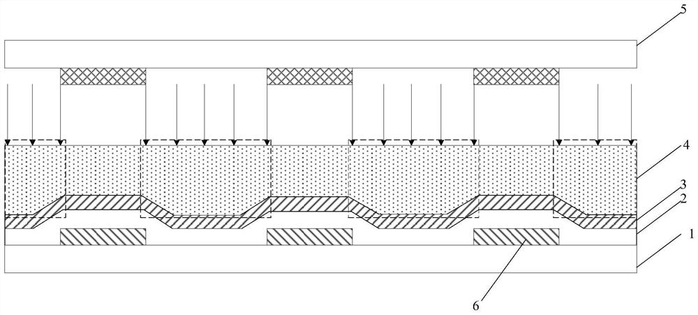
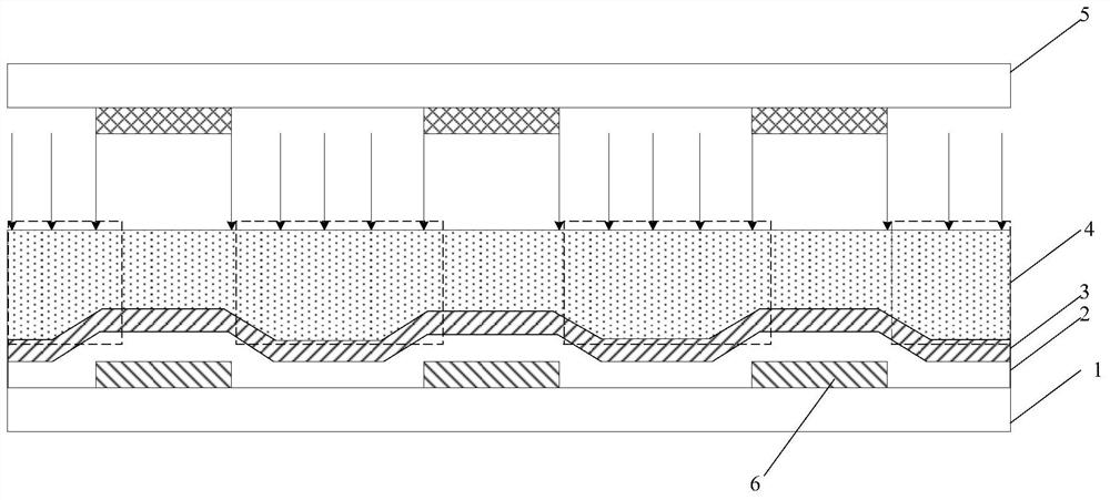
[0051] The existing wiring design uses two layers of metal to overlap to create a fan-out area to reduce the layout space of the signal line. However, when making the upper layer of metal, the thickness of the resist during exposure is different due to the existence of alignment offset. figure 1 is a schematic diagram without alignment shift, figure 2 is a schematic diagram of alignment offset, wherein, 1 is the base substrate, 2 is the insulating layer, 3 is the second metal layer, 4 is the photoresist, 5 is the mask plate, and 6 is the pattern of the first metal layer, because Exposure resolution and uniformity are greatly reduced, the line width of the signal line made of the upper layer metal will become smaller, and the risk of l...


PUM

PropertyMeasurementUnit
transmittivityaaaaaaaaaa

Abstract

The invention provides a display substrate, a manufacturing method thereof, and a display device, belonging to the technical field of display. Wherein, before forming the second metal layer pattern on the insulating layer in the preset area, the manufacturing method of the display substrate includes: removing the raised portion of the insulating layer in the preset area, so that the insulating layer is in the preset area. The surface of the set area is flattened. Through the technical solution of the present invention, the wiring space of the fan-out area can be reduced, which is beneficial to realize the narrow frame of the display device.

Description

technical field [0001] The present invention relates to the field of display technology, in particular to a display substrate, a manufacturing method thereof, and a display device. Background technique [0002] With the development of display technology, display products need to be designed with narrow borders to achieve perfect visual effects. The metal traces on the lower frame of the display product are the peripheral circuits connecting the effective display area of ​​the display panel and the driver chip, which are called fanout signal lines. It is necessary to reduce the line width (Line) and line spacing (Space) of the signal lines in the fanout area. ) to reduce the area occupied by the fan-out area to achieve a narrow border, where the sum of the line width and the line spacing is called fanoutpitch. [0003] The existing wiring design uses two layers of metal to overlap to create a fan-out area to reduce the layout space of the signal line. However, when making th...

Claims


Application Information

Patent Timeline
Patent Type & Authority Patents(China)
IPC IPC(8): G09F9/00G03F7/20
CPCG03F7/70283G09F9/00
Inventor 赵娜元淼王艳沈奇雨张志海尹洋植
Owner HEFEI BOE OPTOELECTRONICS TECH
Learn More