A temperature rise test system and method for a photovoltaic inverter under on-site operating conditions

A technology for photovoltaic inverters and test systems, applied in signal transmission systems, instruments, thermometers, etc., can solve the problems of difficult wiring, interrupted data jumps in temperature measurement, poor scalability, etc., and achieve convenient and flexible installation, reliable insulation monitoring. , the effect of small size

Active Publication Date: 2021-11-19
CHINA ELECTRIC POWER RES INST +3
View PDF8 Cites 0 Cited by
  • Summary
  • Abstract
  • Description
  • Claims
  • Application Information

AI Technical Summary

Problems solved by technology

However, when the surface of the optical fiber is polluted, it will cause discharge along the surface of the optical fiber. In addition, it is easy to break, easy to break, and not resistant to high temperature. Due to the influence of the structure of the switch cabinet, it is difficult to wire in the cabinet.
[0006] Acoustic surface temperature measurement uses passive wireless sensors, but it is limited by the principle of bandwidth slicing and signal simulation processing technology of acoustic surface temperature measurement. Large jumps, too many sensors cannot be installed, otherwise the receiving system cannot distinguish
[0007] Patent CN201210073736 "A Temperature Rise and Efficiency Test System and Method for High-Power Photovoltaic Inverter at Rated Power" proposes to install a temperature sensor on the power unit of the inverter to realize the temperature rise test of the photovoltaic inverter at rated power , but the patent focuses on the inverter efficiency test, and does not explain the temperature sensor type, test principle, specific use method, etc. of the temperature rise test, and the system and method are used in the product development and product delivery experiment stages

Method used


Image

  • A temperature rise test system and method for a photovoltaic inverter under on-site operating conditions
  • A temperature rise test system and method for a photovoltaic inverter under on-site operating conditions
  • A temperature rise test system and method for a photovoltaic inverter under on-site operating conditions

Examples


Embodiment Construction

[0033] The specific embodiments of the present invention will be further described in detail below in conjunction with the accompanying drawings.

[0034] In order to solve the following deficiencies in the prior art:

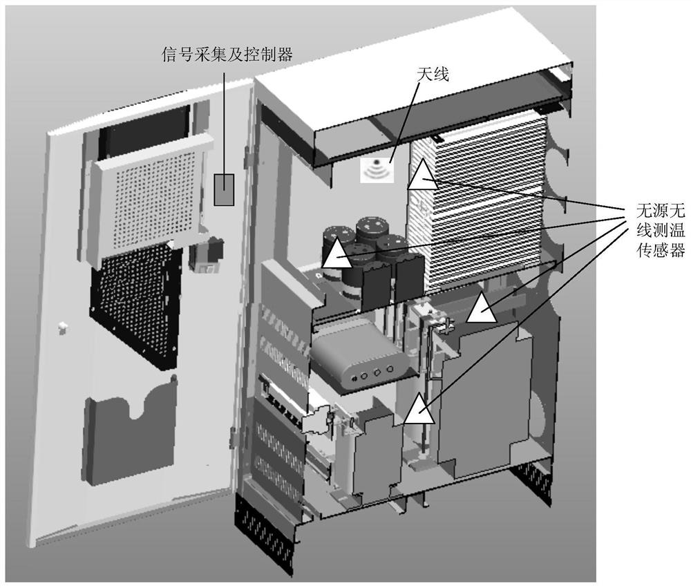
[0035] 1) When the inverter is running normally, the cabinet must be closed, and the traditional active and wired test methods, infrared thermal imager temperature measurement method, etc. cannot be applied;

[0036] 2) The measurement sensor of the optical fiber temperature measurement method is not convenient to install in the narrow space in the inverter cabinet;

[0037] 3) Due to the limitation of irradiation resources, the photovoltaic inverter often cannot reach the rated output power during normal operation, and the temperature rise under the rated output power of the inverter cannot be tested.

[0038] In summary, conventional thermocouples, thermal resistors, semiconductor temperature sensors and other temperature measurement methods are difficult to...


PUM


Abstract

The present invention provides a temperature rise test system and method under on-site operating conditions of a photovoltaic inverter, which includes a signal transmitting and receiving antenna and a signal acquisition controller, and is installed at multiple test points in a photovoltaic inverter cabinet to communicate with the Passive wireless temperature measuring sensors connected to multiple test points in one-to-one correspondence; the passive wireless temperature measuring sensors are connected to the signal acquisition controller in the form of wireless radio frequency through the signal transceiver antenna; the signal acquisition controller also includes a calculation module, the The calculation module is used to calculate the temperature rise of each component in the inverter cabinet according to the results measured by the passive wireless temperature measurement sensor. The scheme adopts the passive wireless sensor of radio frequency identification technology, which can realize the synchronous measurement of multiple external temperature points inside the cabinet and the temperature points outside the cabinet under normal operating conditions of the photovoltaic inverter, and make the inverter The inverter works at the maximum output power operating state, so as to obtain the maximum temperature rise of the inverter.

Description

technical field [0001] The invention belongs to the field of on-site testing of photovoltaic inverters, and in particular relates to a temperature rise testing system and method under on-site operating conditions of photovoltaic inverters. Background technique [0002] In recent years, the photovoltaic industry has developed rapidly. Photovoltaic inverters are one of the core equipment of photovoltaic power generation. Working in the environment of high current and strong magnetic field for a long time, they are prone to local overheating, causing fires and large-scale power outages. However, the climatic conditions in different locations are varied, and the results of laboratory type tests cannot reflect the temperature rise of inverters at the photovoltaic power plant site. In the field of inverter temperature rise test, there are mainly infrared temperature measurement method, optical fiber temperature measurement method and acoustic surface temperature measurement metho...

Claims


Application Information

Patent Timeline
Patent Type & Authority Patents(China)
IPC IPC(8): G01K13/00G08C17/02G01K1/022G01K1/024
CPCG08C17/02G01K13/00
Inventor 丁明昌李红涛刘美茵张双庆董颖华郑飞董玮
Owner CHINA ELECTRIC POWER RES INST
Why Eureka
Try Eureka