Environmental sanitation public garbage bin applied to uneven ground and method
A trash can and floor technology, applied in the field of sanitation trash cans, can solve the problems of poor stability and easy dumping of trash cans, and achieve good impact resistance, good protection, and increased stability
- Summary
- Abstract
- Description
- Claims
- Application Information
AI Technical Summary
Problems solved by technology
Method used
Image
Examples
Embodiment 1
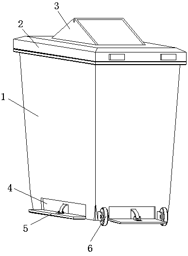
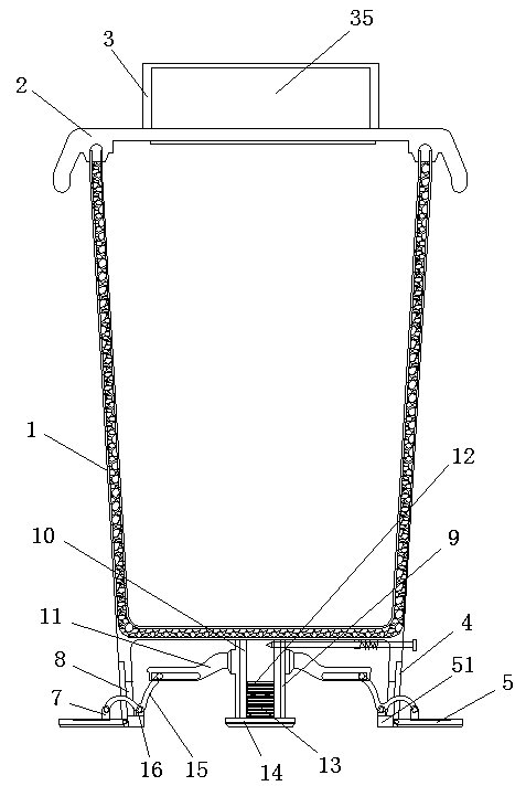
[0030] Example 1: Such as Picture 12 , A sanitation public trash can applied to uneven ground, including a bucket body (1), a bucket lid (2) hinged on the top of the bucket body (1), and two walking wheels (6) installed on the bottom side of the bucket body (1) ), characterized in that: the central position of the top of the barrel cover (2) is provided with an injecting unit (3) for placing garbage, and the central position of the bottom of the four sides of the barrel body (1) is provided with a concave hole (4) The bottom of the barrel body (1) is integrally formed with a compartment, and a top column (10) is vertically arranged downward at the center of the top of the compartment, and the top column (10) is provided with an integrated A sleeve (9) is sleeved on the outer side of the top column (10), the bottom end of the sleeve (9) penetrates the bottom of the barrel (1), and the bottom of the barrel is provided with a sleeve The through hole through which the barrel passe...
Embodiment 2
[0032] Example 2: Please refer to Figure 1-11 , A sanitation public trash can applied to uneven ground, including a bucket body 1, a bucket lid 2 hinged on the top of the bucket body 1, and two walking wheels 6 installed on the bottom side of the bucket body 1, at the center of the top of the bucket lid 2 A discharging unit 3 for discharging garbage is provided. A groove 4 is opened at the center of the bottom of the four sides of the bucket body 1, and a support plate 5 is movably installed at the inner side of the groove 4 and near the bottom end of the bucket body 1. A compartment is integrally formed at the bottom of the barrel body 1, and a top post 10 is vertically arranged downward at the center of the top of the compartment. The top post 10 is provided with an integral convex edge 12, and the outside of the top post 10 is wrapped There is a sleeve 9. The bottom end of the sleeve 9 penetrates the bottom 51 of the barrel body 1 and extends to the outside of the bottom of...
Embodiment 3
[0037] Example 3: Please refer to Figure 1-11 And 13, the injection unit 3 includes two triangular side vertical plates 31 that are parallel and perpendicular to each other. The top ends of the two side vertical plates 31 are connected by a connecting cross bar 32, and the connecting cross bar 32 and the side vertical plate 31 are connected. To set the structure, the cross-section of the connecting cross bar 32 is a "∧"-shaped structure, and the included angle is 90 degrees. The two side vertical plates 31 and the lid 2 are formed as an integral structure. The two side vertical plates 31 A movable sealing plate 35 is provided between the side slopes, and the inner sides of the slopes on both sides of the two side vertical plates 31 are integrally formed with a barrier 33. The bottom of the barrier 33 and the bottom of the lid 2 correspond to two A card slot 34 is opened at the gap between the side vertical plates 31, and the two movable sealing plates 35 each include a plate b...
PUM
 Abstract
Description
Claims
Application Information
 - R&D
- Intellectual Property
- Life Sciences
- Materials
- Tech Scout
- Unparalleled Data Quality
- Higher Quality Content
- 60% Fewer Hallucinations
Browse by: Latest US Patents, China's latest patents, Technical Efficacy Thesaurus, Application Domain, Technology Topic, Popular Technical Reports.
© 2025 PatSnap. All rights reserved.Legal|Privacy policy|Modern Slavery Act Transparency Statement|Sitemap|About US| Contact US: help@patsnap.com


