Post-welding thermal treatment method for hypoeutectoid steel rail

A post-weld heat treatment and hypoeutectoid technology, applied in heat treatment furnaces, heat treatment equipment, furnaces, etc., can solve problems such as endangering driving safety, increasing wheel-rail impact, and affecting the service life of rails

Inactive Publication Date: 2019-02-19
PANZHIHUA IRON & STEEL RES INST OF PANGANG GROUP
View PDF7 Cites 6 Cited by
  • Summary
  • Abstract
  • Description
  • Claims
  • Application Information

AI Technical Summary

Problems solved by technology

The softened rail joints are easy to form "saddle" wear on the rail head tread first during the line service process, which increases the wheel-rail impact, affects the ser...

Method used


Image

  • Post-welding thermal treatment method for hypoeutectoid steel rail
  • Post-welding thermal treatment method for hypoeutectoid steel rail
  • Post-welding thermal treatment method for hypoeutectoid steel rail

Examples


Embodiment 1

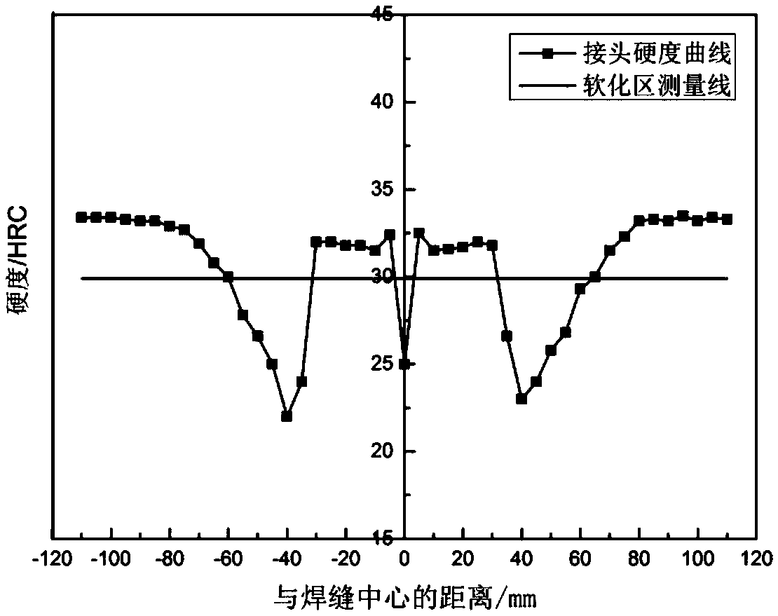
[0038] The hypoeutectoid rail welded joint obtained by flash welding at a temperature of 1400 °C is air-cooled. When the joint is cooled from 1400 °C to 180 °C, the medium-frequency induction profiling electric heating coil is used to heat the entire section of the rail welded joint area; when When the tread temperature of the rail reaches 900°C, the heating is stopped, and then the welded joint of the rail is rapidly cooled to 280°C by spraying compressed air; finally, the welded joint is air-cooled to room temperature (25°C), thereby obtaining the welded Heat-treated hypoeutectoid rail welded joints. The longitudinal hardness data at the position 5mm below the rail head tread of the welded joint is shown in Table 1, and the distribution effect of the longitudinal hardness is as follows figure 1 shown.

[0039] Table 1

[0040]

[0041] From Table 1 and figure 1 It can be seen that when the post-weld heat treatment method provided by the present invention is used to tre...

Embodiment 2

[0043] Air-cool the hypoeutectoid rail welded joint with a temperature of 1300°C obtained by gas pressure welding. When the welded joint is cooled from 1300°C to 200°C, use an oxygen-acetylene flame profiling heater to heat the entire section of the welded joint area of ​​the rail ; Stop heating when the tread temperature of the rail reaches 920°C, then use water mist mixture to air-cool the rail welded joint to 300°C; finally air-cool the welded joint to room temperature (25°C), thereby obtaining the welded joint of the present invention Heat-treated hypoeutectoid rail welded joints. The hardness distribution effect of the welded joint in this embodiment is different from that of figure 1 The effects shown are basically the same, and the metallographic structure of the welded joint is basically the same as that of Example 1. The hypoeutectoid rail welded joint obtained in this example can pass the physical fatigue test with a cycle number of 3 million times.


PUM

PropertyMeasurementUnit
Hardnessaaaaaaaaaa
Hardnessaaaaaaaaaa
Hardnessaaaaaaaaaa

Abstract

The invention relates to a post-welding thermal treatment method for a hypoeutectoid steel rail, belongs to the technical field of railway steel rail welding, and aims to solve the technical problemsof finding the most suitable post-welding thermal treatment method, controlling tread hardness of the hypoeutectoid steel rail to be within a reasonable range, and guaranteeing the service life of thesteel rail welding joint. According to the technical scheme adopted by the invention, the post-welding thermal treatment method comprises the following steps of: performing first-time cooling on a to-be-cooled hypoeutectoid steel rail joint obtained by welding until a temperature lower than 200 DEG C, stopping heating while heating the hypoeutectoid steel rail to a temperature of 840-920 DEG C, performing second-time cooling, stopping second-time cooling while cooling to a temperature of 250-320 DEG C, and performing third-time cooling to a room temperature of 10-40 DEG C. The rail head treadlongitudinal hardness of the post-welded thermally treated welding joint is 90% or more of average hardness of a steel rail base material, abnormal structures such as martensite and bainite are avoided, and the physical fatigue service life of the joint is not less than 3 million of times.

Description

technical field [0001] The invention belongs to the technical field of railway rail welding, in particular to a post-weld heat treatment method for hypoeutectoid rails. Background technique [0002] At this stage, the global railway system mainly covers three types: heavy-haul railway, high-speed railway and mixed passenger and freight railway. The heavy-duty railway train has a heavy axle (axle load 25t-40t), the carbon content of the rail used is usually greater than 0.75%, the tensile strength is above 1200MPa, has a full pearlite structure or is mainly pearlite, and contains a small amount of secondary carburization Body, with high strength, high hardness while ensuring wear resistance. Since the passenger-freight mixed railway has to undertake both passenger transport and cargo transport, it is required that the rails not only have a certain wear resistance, but also have good fatigue resistance. Therefore, the carbon content of rails used in mixed passenger and freig...

Claims


Application Information

Patent Timeline
IPC IPC(8): C21D1/78C21D9/04C21D9/50
CPCC21D1/785C21D9/04C21D9/505
Inventor 白威李大东陆鑫徐飞翔
Owner PANZHIHUA IRON & STEEL RES INST OF PANGANG GROUP
Why Eureka
Try Eureka