
Aviation radial tire

A technology for radial tires and aviation, applied to special tires, tire parts, reinforcement layers of pneumatic tires, etc., can solve the problems of reducing bead durability, bead bursting, bead delamination, etc., to increase mechanical properties, The effect of reducing internal cracks and preventing cord loosening and delamination

Inactive Publication Date: 2019-02-15
T RUBBER
View PDF8 Cites 0 Cited by
  • Summary
  • Abstract
  • Description
  • Claims
  • Application Information

AI Technical Summary

Problems solved by technology

As a result, the durability of the bead is greatly reduced, and in severe cases, it may cause bead delamination, bulging, or even bead bursting.

Method used

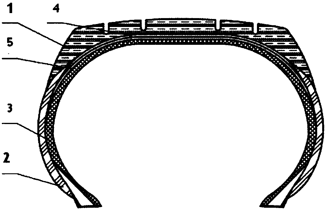

Image

  • Aviation radial tire
  • Aviation radial tire
  • Aviation radial tire

Examples


Embodiment 1

[0022] Such as Figure 1 to 3 As shown, an aviation radial tire includes a carcass, the carcass includes a tread rubber layer 1, a sidewall layer 2, an inner liner layer 3, a bead layer 4 and a crown reinforcement 5, and a tread rubber layer 1 Adhesive layers of different structures are bonded into one body. Between the tread rubber layer 1 and the inner liner 3, a bead layer 4 composed of several traveler rings arranged in parallel and a crown reinforcement member 5 are arranged in sequence. Multiple traveler rings The steel wires are connected together to form a steel wire mesh. The steel wire mesh is provided with a filler rubber strip 401. The crown reinforcement 5 includes a plurality of first belt layers made of carbon cellulose distributed in parallel, on both sides of the first belt layer. It is connected to the sidewall layer 2, the end of the rubber filler strip 401 overlaps the connection between the first belt layer and the sidewall layer 2, and the contact surface ...

Embodiment 2

[0030] Referring to Example 1, the difference between the aero radial tire provided in this example is that the rubber surface layer 101 is made of rubber, and the rubber composition includes the following components by weight: 50 parts of oil-extended rubber, 10 parts of benzene rubber, 25 parts of butadiene rubber, 10 parts of polyisoprene rubber, 20 parts of carbon black, 1 part of zinc stearate; 55 parts of naphthenic rubber oil are filled in every 100 parts of rubber.

Embodiment 3

[0032] Referring to Example 1, the difference between the aero radial tire provided in this example is that the rubber surface layer 101 is made of rubber, and the rubber composition includes the following components by weight: 100 parts of oil-extended rubber, 30 parts of benzene rubber, 30 parts of butadiene rubber, 30 parts of polyisoprene rubber, 40 parts of carbon black, 8 parts of zinc stearate; of which 50 parts of naphthenic rubber oil are filled in every 100 parts of rubber.


PUM

PropertyMeasurementUnit
thicknessaaaaaaaaaa
widthaaaaaaaaaa

Abstract

The invention provides an aviation radial tire. The aviation radial tire comprises a tread part, a belt part, a tire carcass part, an air tight layer, a bead ring layer and a tire crown reinforcing piece; a tread rubber layer is obtained by integrally bonding rubber layers with different structures; the bead ring layer consisting of a plurality of bead rings and the tire crown reinforcing piece are arranged between the tread rubber layer and the air right layer in sequence; the multiple bead rings are connected with each other through steel wires to form a steel wire mesh; a filling rubber strip is arranged on the steel wire mesh; the tire crown reinforcing piece comprises a plurality of first belted layers distributed in parallel and made of carbon cellulose; the two sides of the first belted layers are connected with tire side wall layers; and the tail end of the filling rubber strip is spliced to the connecting parts of the first belted layers and the tire side wall layers. According to the aviation radial tire, problems of large tire side wall deformation and low transverse rigidity can be solved; the bead ring part can be prevented from generating delamination; and a phenomenon that a cord is loose and delaminated at the tail end of a cord fabric layer can be prevented.

Description

Technical field [0001] The invention relates to the technical field of tires, in particular to an aviation radial tire. Background technique [0002] Aviation tires are subjected to extreme operating conditions caused by the combination of the heavy load of the aircraft and the high speed of the aircraft. Due to the heavy load, tires undergo greater deflection than passenger car or truck tires. [0003] Aircraft tires have two common structures: bias and meridian. More than 80% of aircraft tires are biased, which means that they have a carcass made of multiple layers of interlaced plies that form a staggered angle of substantially less than 90 degrees relative to the centerline of the tread. However, as aircraft fuselage manufacturers pursue lighter weight, radial tires have become more common. [0004] Because the carcass and belt cord angles of the current radial aircraft tires are arranged in the radial direction, the carcass cord angle is large, the number of plies is small, t...

Claims


Application Information

Patent Timeline
Patent Type & Authority Applications(China)
IPC IPC(8): B60C9/02B60C9/16B60C9/18B60C1/00C08L21/00C08L91/00C08L9/06C08L9/00C08K3/04C08K5/098
CPCB60C1/0016B60C9/02B60C9/16B60C9/18C08L21/00C08L2205/02C08L2205/025C08L2205/035C08L91/00C08L9/06C08L9/00C08K3/04C08K5/098
Inventor 苏长艳周禹彤丁凯王宇宸
Owner T RUBBER
Learn More