Photon under-sampling system and method for microwave frequency spectrum measurement
A technology of microwave spectrum and undersampling, applied in the field of photon undersampling system for microwave spectrum measurement
- Summary
- Abstract
- Description
- Claims
- Application Information
AI Technical Summary
Problems solved by technology
Method used
Image


Examples
Embodiment 1
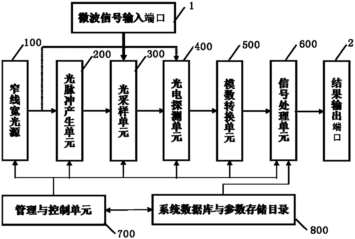
[0069] see figure 1 , is a block diagram of a photon undersampling system for microwave spectrum measurement according to Embodiment 1 of the present invention. Such as figure 1 As shown, the photon undersampling system for microwave spectrum measurement provided by Embodiment 1 of the present invention at least includes:
[0070] A narrow linewidth light source 100 is used to generate an optical carrier. The optical carrier linewidth generated by the narrow linewidth light source 100 is preferably on the order of 100 kHz or less.
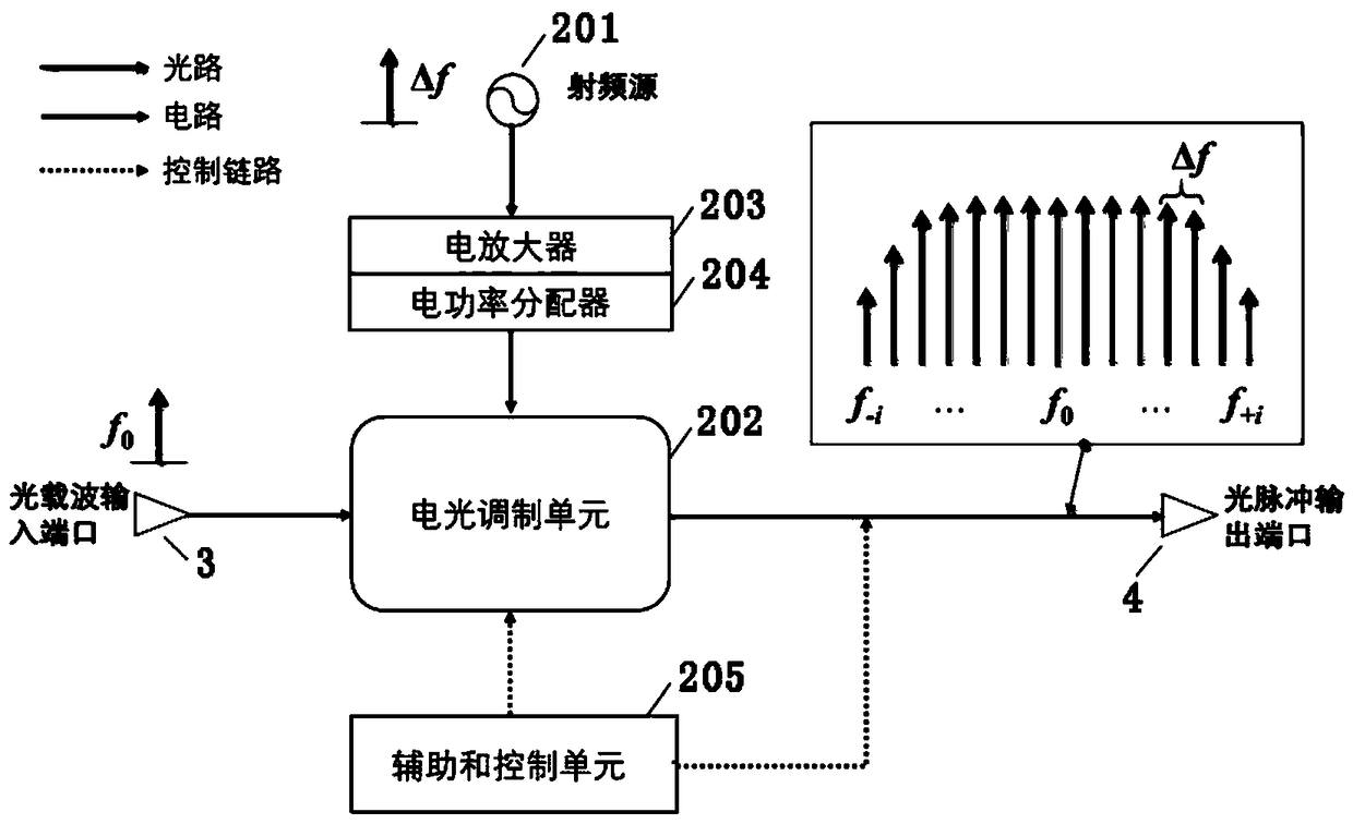
[0071] The optical pulse generation unit 200 is used for analog modulation of the optical carrier by using a radio frequency source with a frequency Δf to generate an optical pulse train with a repetition frequency of Δf, and its spectrum is an optical frequency comb with a comb interval of Δf. The input end of the optical pulse generation unit 200 is connected to the narrow linewidth light source 100, and the optical carrier wave generated by t...
Embodiment 2
[0086] The system configuration of the second embodiment is basically the same as that of the first embodiment, except that a single-channel coherent detection architecture is adopted.
[0087] see Figure 4 , is a structural block diagram of a photon undersampling system oriented to microwave spectrum measurement according to Embodiment 2 of the present invention. The optical sampling unit can be implemented by using an electro-optic intensity modulator 301 , the photoelectric detection unit can be implemented by using a homodyne coherent detector 401 , and the narrow linewidth light source can be implemented by a narrow linewidth laser. The system of this second embodiment also includes:
[0088] An optical power splitter 901, whose input end is connected to the narrow-linewidth laser 101, is used to divide the optical carrier into two outputs, wherein the first signal is input to the optical pulse generation unit 200 to generate an optical pulse train, and the second signa...
Embodiment 3
[0117] The system configuration of the third embodiment is basically the same as that of the second embodiment, the difference is that a multi-channel coherent detection architecture is adopted.
[0118] see Figure 9 , is a structural block diagram of a photon undersampling system for microwave spectrum measurement according to Embodiment 3 of the present invention. The narrow-linewidth light source is implemented by a narrow-linewidth laser array 102 for outputting multi-frequency optical carrier; the optical sampling unit is implemented by an electro-optical intensity modulator 301 . Both the homodyne coherent detector 401 and the analog-to-digital conversion unit 500 are n, and n is the frequency number of the multi-frequency optical carrier.
[0119] The system of this embodiment three also includes:
[0120] An optical power splitter 901, whose input end is connected to the narrow linewidth laser array 301, is used to divide the multi-frequency optical carrier into two...
PUM
 Abstract
Description
Claims
Application Information
 - R&D
- Intellectual Property
- Life Sciences
- Materials
- Tech Scout
- Unparalleled Data Quality
- Higher Quality Content
- 60% Fewer Hallucinations
Browse by: Latest US Patents, China's latest patents, Technical Efficacy Thesaurus, Application Domain, Technology Topic, Popular Technical Reports.
© 2025 PatSnap. All rights reserved.Legal|Privacy policy|Modern Slavery Act Transparency Statement|Sitemap|About US| Contact US: help@patsnap.com