
Photon undersampling system and method for microwave spectrum measurement

A microwave spectrum and undersampling technology, applied in the field of photon undersampling systems for microwave spectrum measurement

Active Publication Date: 2021-01-22
CHINA ACADEMY OF SPACE TECHNOLOGY
View PDF11 Cites 0 Cited by
  • Summary
  • Abstract
  • Description
  • Claims
  • Application Information

AI Technical Summary

Problems solved by technology

[0005] The purpose of the present invention is to solve at least part of the technical problems in the prior art, and to provide a photon undersampling system and method for microwave spectrum measurement

Method used


Image

  • Photon undersampling system and method for microwave spectrum measurement
  • Photon undersampling system and method for microwave spectrum measurement
  • Photon undersampling system and method for microwave spectrum measurement

Examples


Embodiment 1

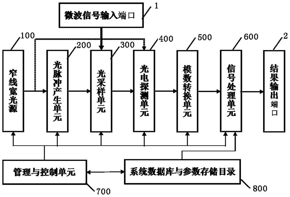
[0069] see figure 1 , is a block diagram of a photon undersampling system for microwave spectrum measurement according to Embodiment 1 of the present invention. Such as figure 1 As shown, the photon undersampling system for microwave spectrum measurement provided by Embodiment 1 of the present invention at least includes:

[0070] A narrow linewidth light source 100 is used to generate an optical carrier. The optical carrier linewidth generated by the narrow linewidth light source 100 is preferably on the order of 100 kHz or less.

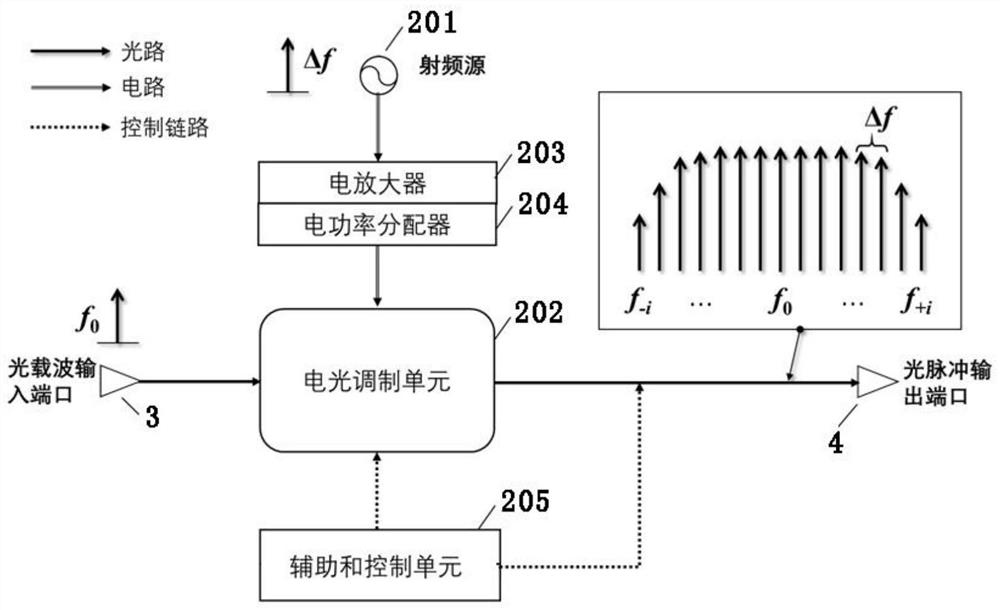
[0071] The optical pulse generation unit 200 is used for analog modulation of the optical carrier by using a radio frequency source with a frequency Δf to generate an optical pulse train with a repetition frequency of Δf, and its spectrum is an optical frequency comb with a comb interval of Δf. The input end of the optical pulse generation unit 200 is connected to the narrow linewidth light source 100, and the optical carrier wave generated by t...

Embodiment 2

[0086] The system configuration of the second embodiment is basically the same as that of the first embodiment, except that a single-channel coherent detection architecture is adopted.

[0087] see Figure 4 , is a structural block diagram of a photon undersampling system oriented to microwave spectrum measurement according to Embodiment 2 of the present invention. The optical sampling unit can be implemented by using an electro-optic intensity modulator 301 , the photoelectric detection unit can be implemented by using a homodyne coherent detector 401 , and the narrow linewidth light source can be implemented by a narrow linewidth laser. The system of this second embodiment also includes:

[0088] An optical power splitter 901, whose input end is connected to the narrow-linewidth laser 101, is used to divide the optical carrier into two outputs, wherein the first signal is input to the optical pulse generation unit 200 to generate an optical pulse train, and the second signa...

Embodiment 3

[0117] The system configuration of the third embodiment is basically the same as that of the second embodiment, the difference is that a multi-channel coherent detection architecture is adopted.

[0118] see Figure 9 , is a structural block diagram of a photon undersampling system for microwave spectrum measurement according to Embodiment 3 of the present invention. The narrow-linewidth light source is implemented by a narrow-linewidth laser array 102 for outputting multi-frequency optical carrier; the optical sampling unit is implemented by an electro-optical intensity modulator 301 . Both the homodyne coherent detector 401 and the analog-to-digital conversion unit 500 are n, and n is the frequency number of the multi-frequency optical carrier.

[0119] The system of this embodiment three also includes:

[0120] An optical power splitter 901, whose input end is connected to the narrow linewidth laser array 301, is used to divide the multi-frequency optical carrier into two...


PUM


Abstract

The invention relates to a photon under-sampling system and method for microwave frequency spectrum measurement. The system comprises a narrow-line-width light source, an optical pulse generating unit, an optical sampling unit, a photoelectric detection unit, an analog-digital conversion unit and a signal processing unit, wherein the optical pulse generating unit is used for carrying out analog modulation on an optical carrier wave generated by the narrow-line-width light source by using a radio-frequency source with a frequency delta f to generate an optical pulse string with a repetition frequency delta f, and an optical spectrum of the optical pulse string is an optical frequency comb with a comb tooth interval delta f; the optical sampling unit is used for carrying out optical samplingon a microwave frequency spectrum signal input through a microwave signal input port by utilizing the optical pulse string, so that the microwave frequency spectrum signal is up-converted to the optical frequency comb; and then measurement information of a to-be-measured microwave frequency spectrum is obtained through the photoelectric detection unit, the analog-digital conversion unit and the signal processing unit. The optical pulse string with the rate far smaller than the Nyquist rate is used for carrying out optical sampling on the broadband microwave signal, without the bandwidth limitation of a high-speed electronic device.

Description

technical field [0001] The invention relates to the technical field of microwave spectrum measurement, in particular to a photon undersampling system and method for microwave spectrum measurement. Background technique [0002] In recent years, with the rapid growth of wireless communication traffic and the continuous upgrading of military defense requirements, as well as the gradual development of other microwave application fields (Internet of Things, medical sensing, new energy, etc.), the utilization of the current electromagnetic spectrum space is becoming more and more serious. more and more complicated. In order to improve the utilization efficiency of low-frequency band resources and effectively and rationally develop and utilize high-band resources, various application scenarios put forward higher and more diverse requirements for broadband microwave spectrum detection, mainly including larger detection bandwidth, higher Detection efficiency, higher resolution, larg...

Claims


Application Information

Patent Timeline
Patent Type & Authority Patents(China)
IPC IPC(8): G01R23/17G01R23/167G01R23/12
CPCG01R23/12G01R23/167G01R23/17
Inventor 高光宇梁启军刘乃金
Owner CHINA ACADEMY OF SPACE TECHNOLOGY
Learn More