A kind of rotating shaft and rotating shaft processing method

A processing method and shaft technology, applied to shafts and bearings, shafts, bearings, etc., can solve problems such as poor impact resistance, poor fatigue resistance, wear of transmission shafts, etc., to achieve easy processing, eliminate processing stress, and reduce processing deformation effect

Active Publication Date: 2020-01-24
安徽俊康泰电子科技有限公司
View PDF13 Cites 0 Cited by
  • Summary
  • Abstract
  • Description
  • Claims
  • Application Information

AI Technical Summary

Problems solved by technology

[0002] The rotating shaft, as the name implies, is the shaft that must be used to connect the main parts of the product and is used to bear both bending moment and torque in the rotating work. The wear of the rotating shaft is a common equipment problem during the use of the shaft, mainly due to the metal characteristics of the shaft. Caused by: Although the metal has high hardness, it has poor yield, poor impact resistance, and poor fatigue resistance, so it is easy to cause adhesive wear, abrasive wear, fatigue wear, fretting wear, etc.
Most of the shaft wear is not easy to detect. It will only be noticed when the machine has high temperature, large beating range, abnormal noise, etc., but when people notice it, most of the drive shafts are worn out, which causes the machine to stop. We propose a shaft and shaft machining method to solve the above problems

Method used


Image

  • A kind of rotating shaft and rotating shaft processing method
  • A kind of rotating shaft and rotating shaft processing method
  • A kind of rotating shaft and rotating shaft processing method

Examples


Embodiment Construction

[0028] In order to make the object, technical solution and advantages of the present invention clearer, the present invention will be further described in detail below through the accompanying drawings and embodiments. However, it should be understood that the specific embodiments described here are only used to explain the present invention, and are not intended to limit the scope of the present invention.

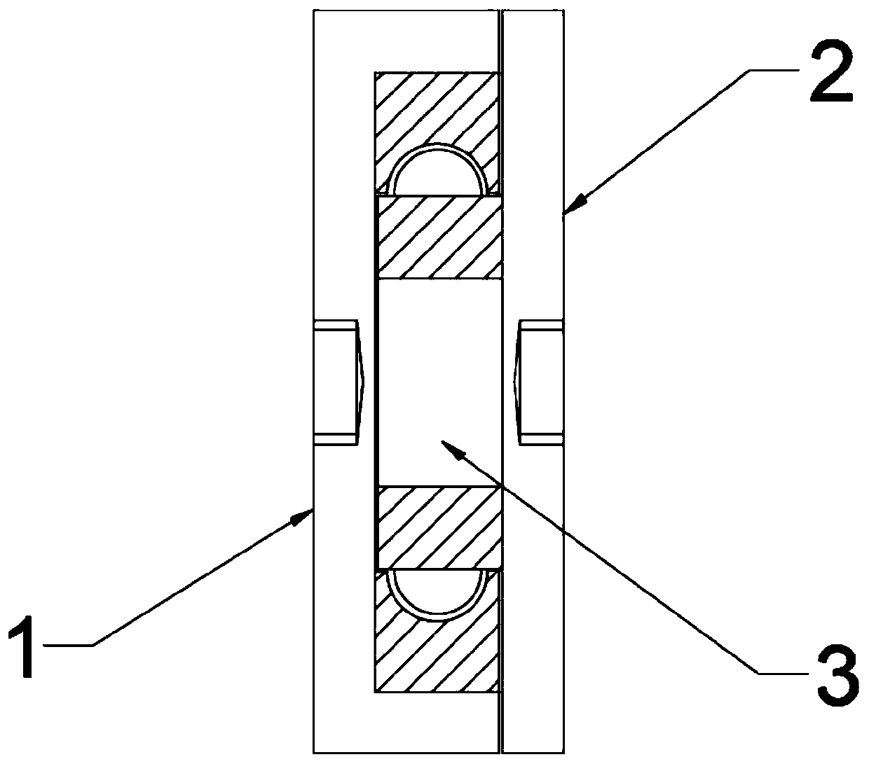
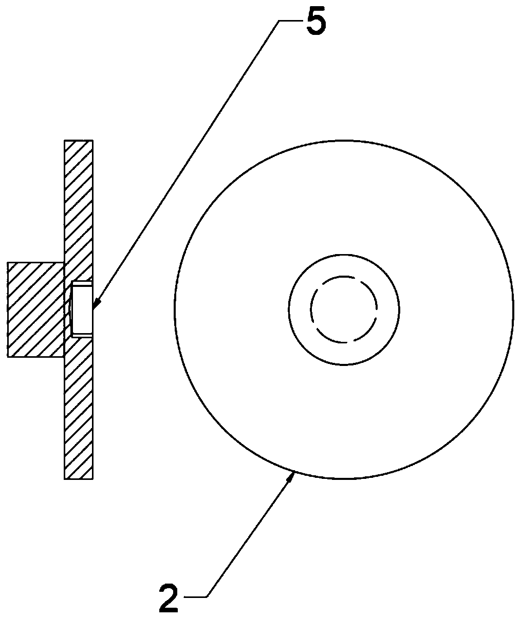
[0029] see Figure 1-4 , the present invention provides a rotating shaft and a method for processing the rotating shaft, comprising the following steps:

[0030] (1) Rough turning: use the fixture to clamp the forging blank, correct the outer circle runout of 0-0.5mm and the inner circle runout of 0-1.6mm, carry out rough turning processing according to the processing technology drawing, and control the height of the single circle of the outer diameter of the shaft The error is not more than 0.8mm;

[0031] (2) Semi-finishing turning: use fixtures to clamp the forgings ...


PUM


Abstract

The invention discloses a rotation shaft and a rotation shaft machining method. The method comprises the following steps including rough turning, half finish turning, heat treatment, finish turning, heat treatment, fine grinding, lineation, drilling, tapping, heat treatment, assembling and warehousing. The invention discloses a shaft body machining technology. Three heat treatment technologies anda heat sleeve assembling technology are adopted, compared with a traditional machining technology, the first heat treatment technology and the second heat treatment technology adopt stress relief annealing, machining stress generated in each pass of machining is eliminated, the third heat treatment technology adopts the normalizing technology, tempering treatment is replaced, cost is reduced, andfinally the heat sleeve technology is adopted so that a shaft body can be in interference fit with the inner circle face and the outer circle face of a bearing. By usage of the shaft body machining method, the machining difficulty can be lowered, the service life of machining machines is prolonged, meanwhile, energy consumption can be reduced, the machining cost is reduced, and the quality of theshaft body is improved.

Description

technical field [0001] The invention relates to a technical field related to mechanical processing technology, in particular to a rotating shaft and a processing method for the rotating shaft. Background technique [0002] The rotating shaft, as the name implies, is the shaft that must be used to connect the main parts of the product and is used to bear both bending moment and torque in the rotating work. The wear of the rotating shaft is a common equipment problem during the use of the shaft, mainly due to the metal characteristics of the shaft. Caused: Although the metal has high hardness, it has poor yield, poor impact resistance, and poor fatigue resistance, so it is easy to cause adhesive wear, abrasive wear, fatigue wear, and fretting wear. Most of the shaft wear is not easy to detect. It will only be noticed when the machine has high temperature, large beating range, abnormal noise, etc., but when people notice it, most of the drive shafts have been worn out, causing ...

Claims


Application Information

Patent Timeline
Patent Type & Authority Patents(China)
IPC IPC(8): B23P15/00F16C3/02
CPCB23P15/00F16C3/02F16C2220/60F16C2220/62F16C2223/02
Inventor 汤礼进陈志明丁娜丁丁周志芳
Owner 安徽俊康泰电子科技有限公司
Why Eureka
Try Eureka