Laser melting deposition method of ceramic reinforced high-entropy alloy composite component
A composite material component, laser melting deposition technology, applied in the direction of additive processing, energy efficiency improvement, process efficiency improvement, etc., can solve the constraints of ceramic reinforced high entropy alloy composite component preparation and application, ceramic reinforced high entropy alloy composite There are many steps in material components, uneven distribution of reinforcement phases, etc., to achieve the effect of controllable internal structure, solving poor internal quality, and uniform distribution of reinforcement phases
- Summary
- Abstract
- Description
- Claims
- Application Information
AI Technical Summary
Problems solved by technology
Method used
Image
Examples
example 1
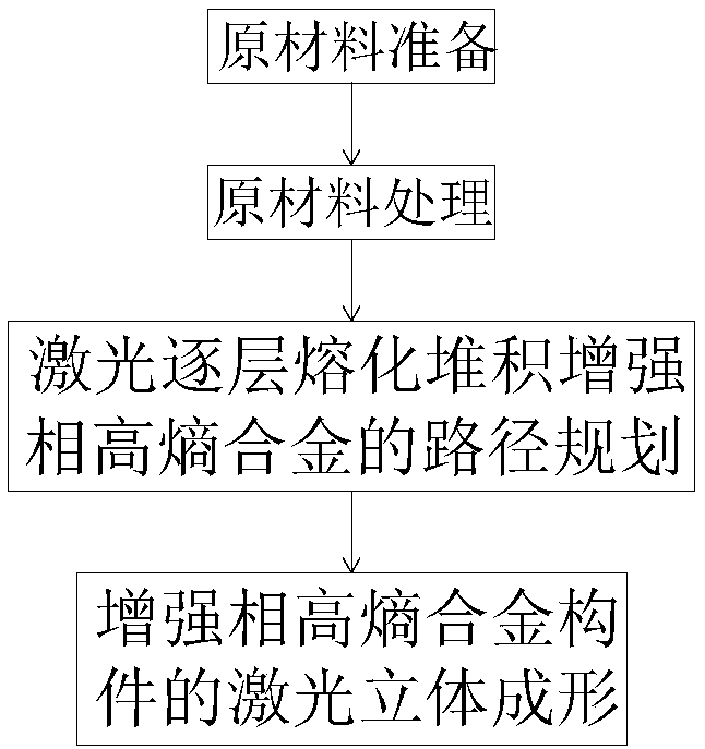
[0041] In this example, the laser melting deposition method is used to prepare a single-wall ceramic reinforced high-entropy alloy composite component. The process includes the following steps:
[0042] (1) Preparation of raw materials:
[0043] FeCoNiCrMn spherical alloy powder with an average particle size of 100 μm, WC spherical ceramic powder with an average particle size of 10 μm, stainless steel substrate;
[0044] (2) Raw material handling:
[0045] Mix FeCoNiMnCr-like spherical alloy powder and WC-like spherical ceramic powder at an atomic ratio of 9:1, bake in a vacuum oven at 120°C for 2 hours, then cool naturally, and put it into the barrel of the powder feeder after cooling; use No. 800 sandpaper Mechanically grind the stainless steel substrate, and immerse the polished substrate in acetone in a beaker, and then place them together in an ultrasonic cleaning device for cleaning, and then repeat the steps of grinding, immersion, and cleaning at least once, and the c...
example 2
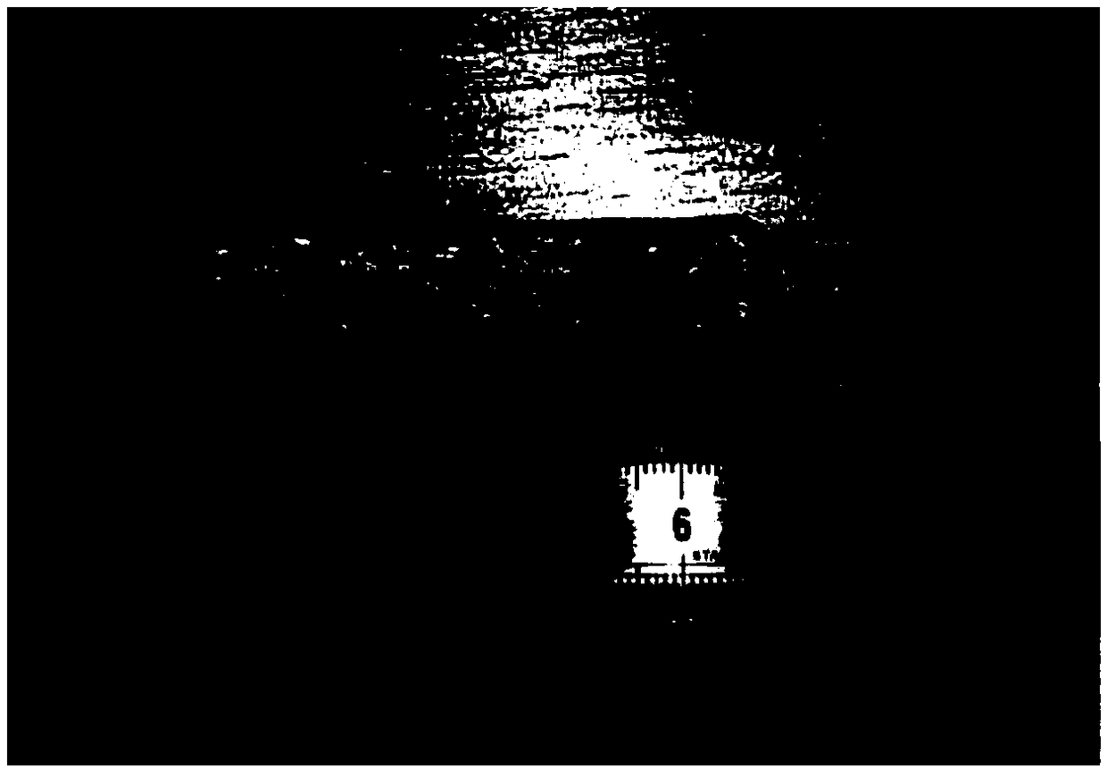
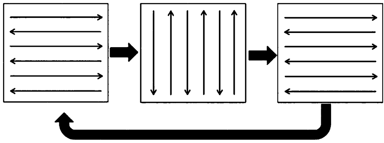
[0053] This example uses the laser melting deposition preparation method to prepare ceramic reinforced high-entropy alloy composite component blocks. The process uses the same powder and laser additive manufacturing process as Example 1. The difference lies in path planning and code generation: The 3D model of the block is layered and sliced, and each layer can be overlapped by single-line scanning. The single-channel overlapping rate of each layer is 30% to 60%. After each layer is completed, the Z-axis of the machine tool is raised by a certain amount. The height continues to scan and accumulate, but the scanning direction is perpendicular to the previous layer, so that the circular accumulation becomes a block, that is, the scanning and melting deposition is performed like a checkerboard, such as image 3 shown. Finally, the ceramic reinforced high-entropy alloy composite component block sample is obtained, as shown in Figure 4 shown.
PUM
| Property | Measurement | Unit |
|---|---|---|
| particle size | aaaaa | aaaaa |
| thickness | aaaaa | aaaaa |
| particle size | aaaaa | aaaaa |
Abstract
Description
Claims
Application Information
 - R&D Engineer
- R&D Manager
- IP Professional
- Industry Leading Data Capabilities
- Powerful AI technology
- Patent DNA Extraction
Browse by: Latest US Patents, China's latest patents, Technical Efficacy Thesaurus, Application Domain, Technology Topic, Popular Technical Reports.
© 2024 PatSnap. All rights reserved.Legal|Privacy policy|Modern Slavery Act Transparency Statement|Sitemap|About US| Contact US: help@patsnap.com


