
Invisible glass shaping method

A technology of glass and quartz glass, which is applied in the direction of chemical instruments and methods, glass/slag layered products, coatings, etc., which can solve the problem of not being able to meet the requirements of equipment, the inability to meet the stealth characteristics of multi-base station radars, and the reduction of visible light transmission characteristics, etc. question

Active Publication Date: 2019-01-25
BEIJING HANGBO NEW MATERIAL TECH
View PDF5 Cites 3 Cited by
  • Summary
  • Abstract
  • Description
  • Claims
  • Application Information

AI Technical Summary

Problems solved by technology

However, such glass cannot meet the stealth characteristics of multi-base station radar detection.
(2) Doping wave-absorbing material particles in the glass body or bonding material, using the wave-absorbing material to reduce the reflection intensity of electromagnetic waves; but in order to achieve a specific reflection gain, the concentration characteristics of the wave-absorbing material need to meet specific requirements, and this will The light transmission characteristics of glass are greatly reduced, so that the light transmission characteristics of visible light are reduced; and the absorbing material itself can only realize the absorption of electromagnetic waves in specific frequency bands, that is, glass can only realize the stealth of radar in specific frequency bands
[0004] At present, stealth glass with metamaterial structure has been applied in some equipment, and is set to a specific thickness; however, in practical applications, the stealth glass in different equipment needs to be set to different thicknesses, while the current Most of the invisible glass of the structure can only be set to a specific thickness, which cannot meet the needs of equipment

Method used


Image

  • Invisible glass shaping method
  • Invisible glass shaping method
  • Invisible glass shaping method

Examples


Embodiment Construction

[0034] The application will be further described in detail below with reference to the drawings and embodiments. It can be understood that the specific embodiments described here are only used to explain the related invention, but not to limit the invention. In addition, it should be noted that, for ease of description, only the parts related to the relevant invention are shown in the drawings.

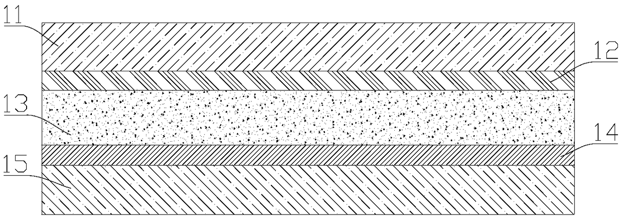
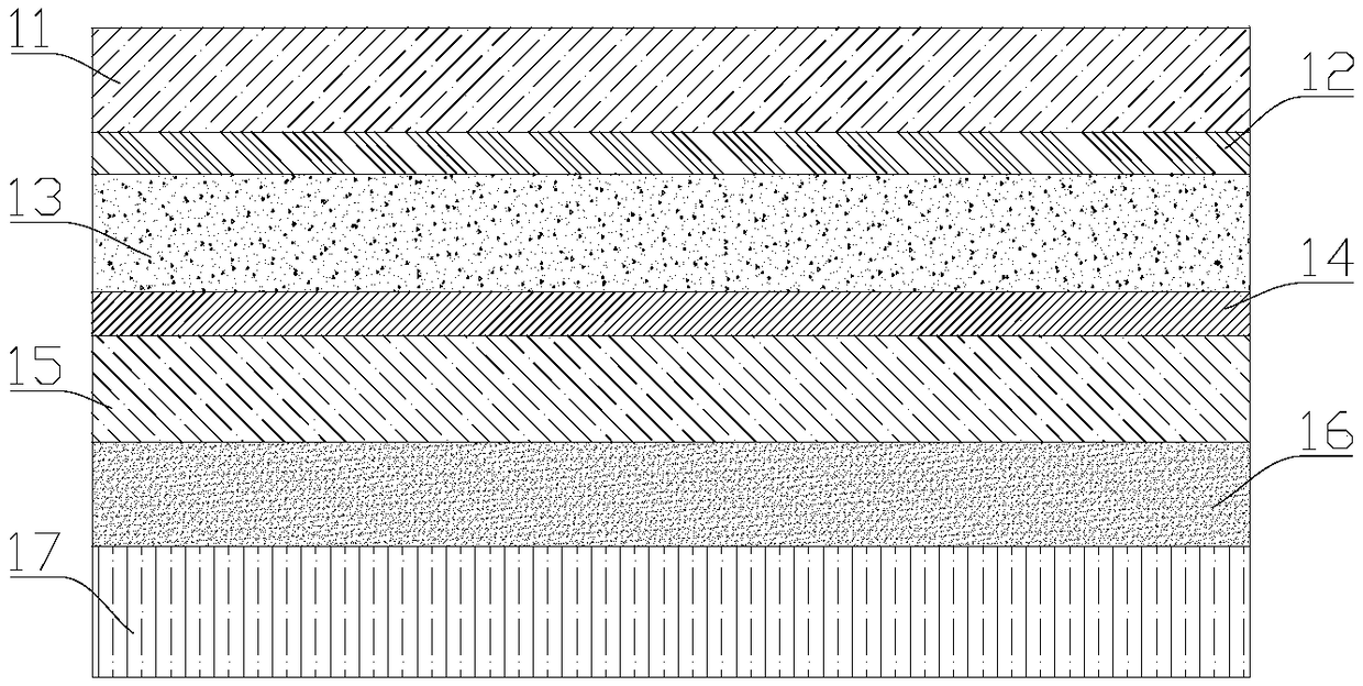
[0035] figure 1 It is a schematic cross-sectional view of the stealth glass provided by the embodiment of the present application. Such as figure 1 As shown, the stealth glass provided by the embodiment of the present application includes a first protective layer 11 on the outer side, a second protective layer 15 on the inner side, and a metamaterial sandwiched between the first protective layer 11 and the second protective layer 15. The structural layer 12, the first transition layer 13, and the radar wave reflection layer 14. The foregoing various layer structures are all light-trans...


PUM


Abstract

The invention provides an invisible glass shaping method which comprises the steps of determining the thickness D of a first transition layer according to the preset thickness and the thicknesses of afirst protection layer, a metamaterial structure layer, a radar wave reflection layer and a second protection layer; determining the thicknesses and dielectric constants of all layers of transparentmedia which form the first transition layer. The invisible glass shaping method disclosed by the invention can determine the thickness of the first transition layer in the invisible glass according torequirements of actual equipment, and can make the invisible glass reach the corresponding degree of invisible characteristic, thus meeting different equipment application requirements.

Description

Technical field [0001] This application relates to the technical field of reducing the reflection of electromagnetic radiation, in particular to a method for shaping stealth glass. Background technique [0002] In some special application environments, especially in the battlefield application environment, the equipment needs to have stealth characteristics, that is, it has the characteristics of reducing the detection by the enemy’s radar through specific processing of the enemy’s electromagnetic waves; and in most equipment (especially It is in personnel-operated equipment). In order for the operator to observe the environment and operate the equipment, the equipment needs glass windows with light-transmitting characteristics. [0003] In order to reduce the characteristics found by radar and meet the requirements of specific light transmission characteristics at the same time, the glass in the glass windows of the aforementioned equipment has been specially treated, and the spec...

Claims


Application Information

Patent Timeline
IPC IPC(8): B32B17/10B32B27/30B32B27/40B32B33/00B32B7/10C03C17/23C03C27/12
CPCB32B17/064B32B7/10B32B27/306B32B27/40B32B33/00B32B2307/20C03C17/23C03C2217/231
Inventor 黄友奇吴志远
Owner BEIJING HANGBO NEW MATERIAL TECH
Learn More