
Metallurgy clamping pipe welding fixing device

A fixing device and pipe clamping technology, used in auxiliary devices, welding equipment, auxiliary welding equipment, etc., can solve the problems of large water supply, incomplete equipment performance, and single overall water supply method, so as to facilitate welding and reduce welding seam errors. The effect of margins

Pending Publication Date: 2019-01-25
阿尔法(江苏)重工科技有限公司
View PDF0 Cites 2 Cited by
  • Summary
  • Abstract
  • Description
  • Claims
  • Application Information

AI Technical Summary

Problems solved by technology

[0002] Industrial production, especially the metallurgical industry, consumes a lot of water. From the current point of view, most of my country's metallurgical industry production enterprises use a circular water supply system. This type of water supply system is convenient, efficient, and easy to handle. characteristics, but the main problem is small water point and large water supply
The circulating water supply system is simple in structure, and the water supply method adopted in use is one pump and one machine, and the overall water supply method is single
The circulating water supply system used by some metallurgical enterprises in the production process only has a single water supply equipment. Therefore, when carrying out metallurgical operations, there are many water points but small water consumption, which is difficult to meet the basic production needs.
In addition, the metallurgical industry water has certain water safety requirements, but the enterprise adopts this water supply design, the overall water supply method is single, and the equipment performance is not complete, which is prone to failure problems in the production process
Outdoor metallurgical pipelines are difficult to be transported to the construction site as a whole. Generally, they are connected by welding after section transportation. When welding in the field, there are many influencing factors. Uniform, prone to stress corrosion, resulting in leakage of the pipeline over a long period of use

Method used


Image

  • Metallurgy clamping pipe welding fixing device
  • Metallurgy clamping pipe welding fixing device

Examples


Embodiment Construction

[0027] In order to make the object, technical solution and advantages of the present invention clearer, the present invention will be further described in detail below in conjunction with the accompanying drawings and embodiments. It should be understood that the specific embodiments described here are only used to explain the present invention, not to limit the present invention. In addition, unless otherwise defined, the technical terms or scientific terms used herein shall have the usual meanings understood by those skilled in the art to which the present invention belongs. "First", "second" and similar words used in the patent application specification and claims of the present invention do not indicate any order, quantity or importance, but are only used to distinguish different components. Likewise, "a" or "a" and the like do not necessarily imply a numerical limitation. "Comprising" or "comprising" and similar words mean that the elements or items appearing before the ...


PUM


Abstract

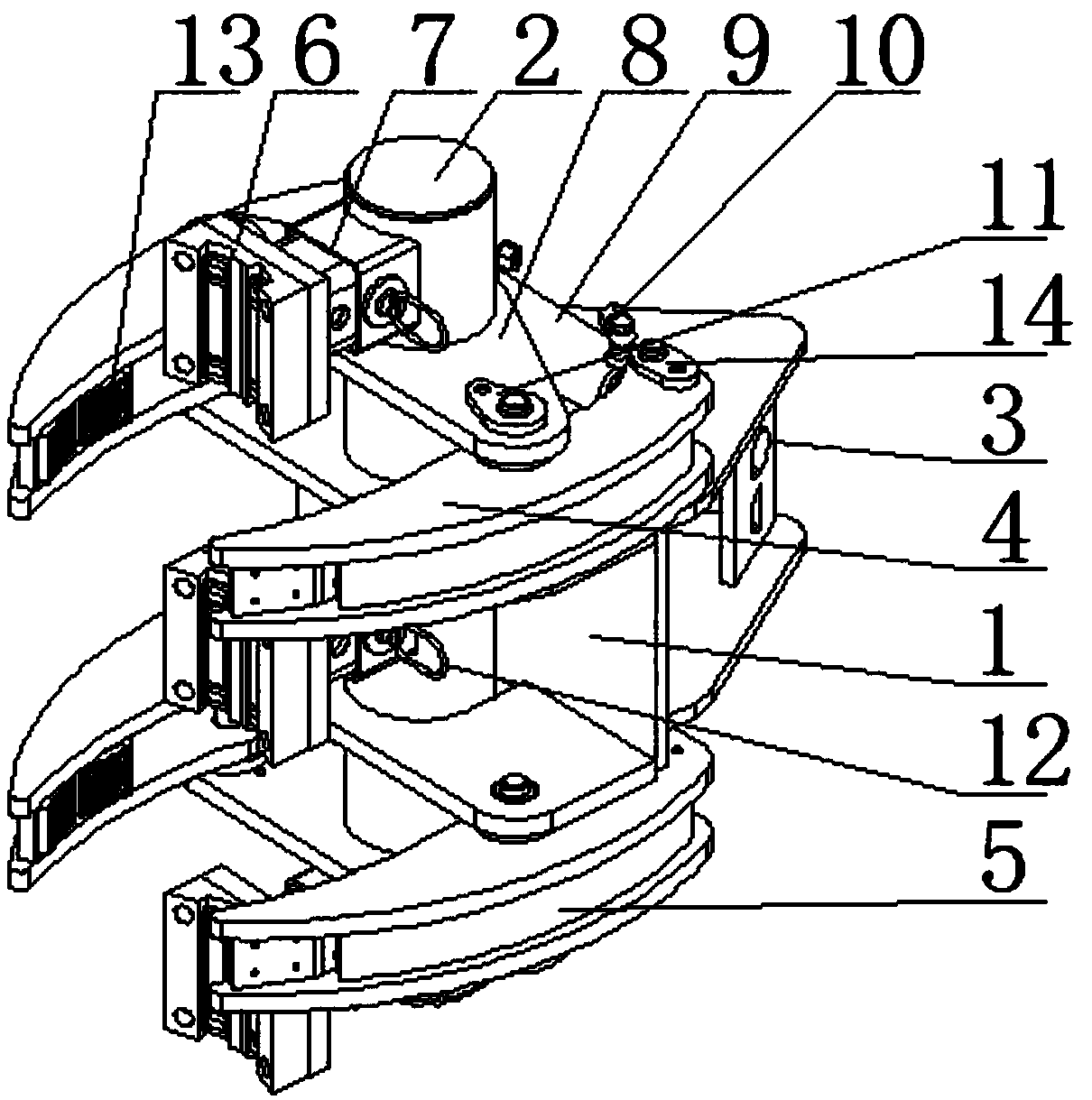
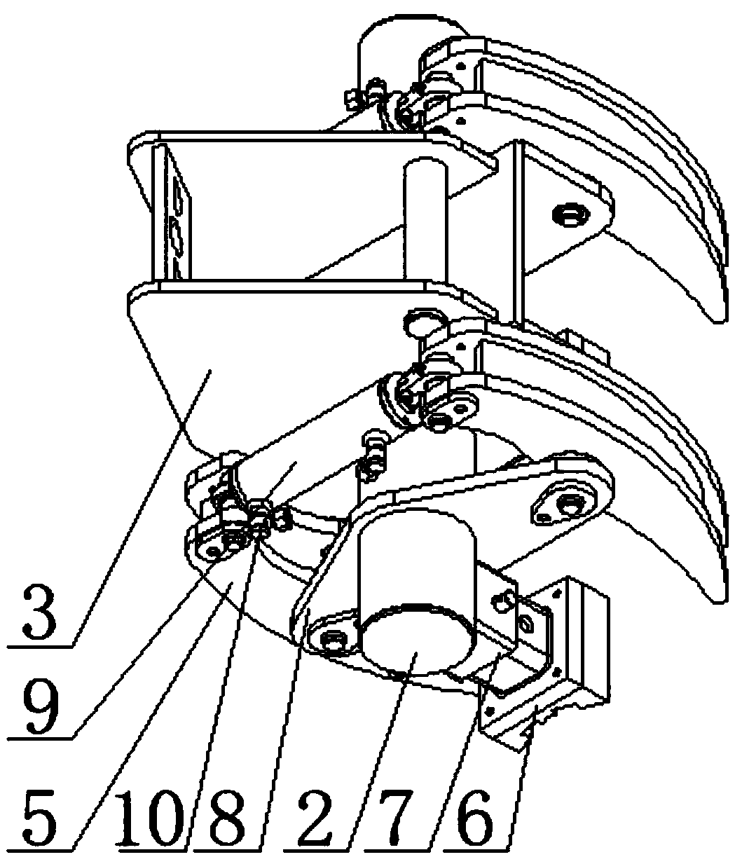
The invention relates to the technical field of metallurgy tools, in particular to a metallurgy clamping pipe welding fixing device. The device comprises a pipe wrench frame and a guide column runninginto the pipe wrench frame. At least one set of clamping assemblies are installed on the guide column. Supporting pieces matched with the clamping assemblies are arranged on the guide column; according to the metallurgy clamping pipe welding fixing device, by arranging a plurality of clamping assemblies controlled by a hydraulic cylinder to be clamped, pipeline connectors are synchronously clamped and fixed conveniently, welding is facilitated, and the welding line alignment tolerance is lowered. By arranging a supporting assembly, the device can fix pipelines of different sizes by adjustingthe length of the supporting assembly on the condition that the clamping range of the clamping assemblies is determined. By arranging positioning pieces on the clamping assemblies, after the pipelineis preliminarily fixed, the clamping assemblies are locked through the positioning pieces, and the phenomenon that the clamping assemblies are loosened due to fatigue of the hydraulic cylinder and therefore pipeline assembling failure is caused is avoided.

Description

technical field [0001] The invention relates to the technical field of metallurgical tools, in particular to a welding and fixing device for metallurgical pinch pipes. Background technique [0002] Industrial production, especially the metallurgical industry, consumes a lot of water. From the current point of view, most of my country's metallurgical industry production enterprises use a circular water supply system. This type of water supply system is convenient, efficient, and easy to handle. characteristics, but the main problem is the small water point and large water supply. The circulating water supply system is simple in structure, and the water supply method adopted in use is one pump and one machine, and the overall water supply method is single. The circulating water supply system used by some metallurgical enterprises in the production process only has a single water supply equipment. Therefore, when carrying out metallurgical operations, there are many water point...

Claims


Application Information

Patent Timeline
Patent Type & Authority Applications(China)
IPC IPC(8): B23K37/053
CPCB23K37/053
Inventor 姚国强
Owner 阿尔法(江苏)重工科技有限公司
Learn More