
Response time testing system and method for digital instrument control system of nuclear power plant

A technology of response time and instrument control system, applied in the direction of digital variable/waveform display, instruments, measuring devices, etc., can solve the problems of large human operation error, limited distance of measuring points, large size of test equipment, etc., to achieve strong adaptability, Simple operation, reducing the effect of human error

Active Publication Date: 2019-01-18
CHINA TECHENERGY +1
View PDF5 Cites 4 Cited by
  • Summary
  • Abstract
  • Description
  • Claims
  • Application Information

AI Technical Summary

Problems solved by technology

[0003] In view of the above-mentioned analysis, the present invention aims to provide a response time testing system and method of a nuclear power digital instrument control system, which is used to solve the problems caused by the use of oscilloscopes in existing testing methods, such as excessive human operation errors, excessively large test equipment, and the Point-distance limited problem

Method used


Image

  • Response time testing system and method for digital instrument control system of nuclear power plant
  • Response time testing system and method for digital instrument control system of nuclear power plant
  • Response time testing system and method for digital instrument control system of nuclear power plant

Examples


Embodiment 1

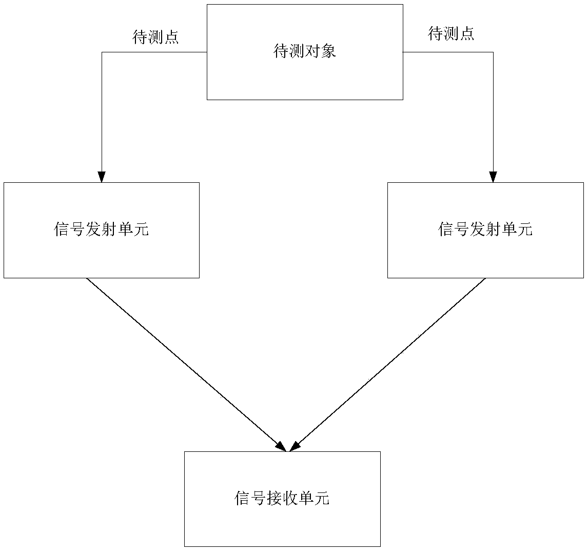
[0044] A specific embodiment of the present invention discloses a response time test system of a nuclear power digital instrument control system. Such as figure 1 As shown, it includes a signal transmitting unit and a signal receiving unit;

[0045] The signal transmitting unit is connected to the point to be tested, and when it is detected that a test signal passes through the point to be measured of the object to be tested, the light source signal is emitted outward; the test signal is a high-frequency pulse signal;

[0046] The signal receiving unit is used to receive the light source signal transmitted by the signal transmitting unit, record the receiving time at the same time, and calculate the difference of the receiving time as the response time of the object to be measured.

[0047] During implementation, the signal transmitting unit sends and collects signals through optical components, and the signals are uploaded to the processor of the signal receiving unit, and t...

Embodiment 2

[0068] Disclosed is a method for testing the response time of a nuclear power digital instrument control system using the system in Embodiment 1, such as Figure 6 shown, including the following steps:

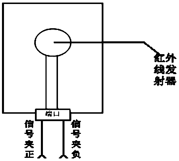
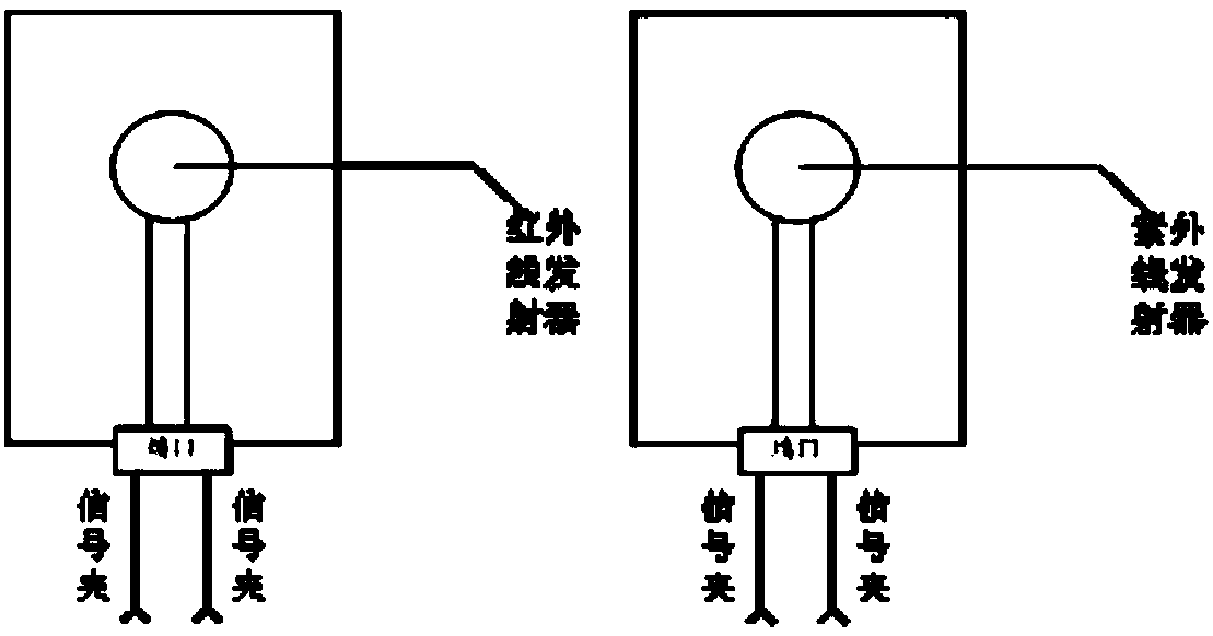
[0069] Step S1, paste two signal transmitting units on the surface of the object to be measured, and connect to the two points to be measured of the object to be measured through the signal clip;

[0070] Step S2, placing a signal receiving unit between two signal transmitting units;

[0071] Step S3, generating a test signal, and making the test signal pass through two points to be tested;

[0072] Step S4, after the two signal transmitting units detect the above-mentioned test signal, respectively transmit the light source signal outward;

[0073] Step S5, the signal receiving unit receives the light source signals emitted by the two signal transmitting units, and records the receiving time at the same time; and calculates the difference between the above two receiving tim...


PUM


Abstract

The invention relates to a response time testing system and method for a digital instrument control system of a nuclear power plant and belongs to the technical field of test of nuclear power systems,which solves the problem of a too large artificial operation error, an oversized testing device and a limited distance between measuring points brought by using an oscilloscope in the existing testing method. The response time testing system comprises a signal emission unit and a signal receiving unit; the signal emission unit is connected with a to-be-tested point; when detecting that a test signal passes through the to-be-tested point, a light source signal is externally emitted; the test signal is a high-frequency pulse signal; the signal receiving unit is used for receiving the light source signal emitted by the signal emission unit, meanwhile, recording the receiving time and calculating a difference value of the receiving time as response time. According to the system and the method, during test, the device is portable and compact; the suitability to the test environment is strong; meanwhile, the test process is simple in operations, thereby reducing the impact of human factorson the test result; moreover, the test cost is greatly reduced, and the economy is strong.

Description

technical field [0001] The invention relates to the technical field of nuclear power system testing, in particular to a response time testing system and method of a nuclear power digital instrument control system. Background technique [0002] The functions realized by the digital instrument and control products of nuclear power plants are relatively complex, and there are many parameters related to the response time (that is, the time difference of signals) in the whole system. These parameters are very important to improve the reliability of the system, so they must be tested and verified. At this stage, our test method for testing time difference parameters is relatively simple, and basically we can only use an oscilloscope to measure it. Although this method is simple to implement and has high real-time performance, the following problems are gradually exposed in the actual use process: First, with the technology The functions of the developed oscilloscope are becoming m...

Claims


Application Information

Patent Timeline
Patent Type & Authority Applications(China)
IPC IPC(8): G01R13/00
CPCG01R13/00
Inventor 谷宇冀建伟黄君龙曹宗生
Owner CHINA TECHENERGY
Learn More