
Multi-beam multiphoton microscopic imaging device

A microscopic imaging and multiphoton technology, applied in the field of optics, can solve the problems of low imaging time resolution and inability to observe biochemical dynamics, and achieve the effect of improving imaging speed

Active Publication Date: 2019-01-15
北京卓奥友科技有限公司
View PDF6 Cites 4 Cited by
  • Summary
  • Abstract
  • Description
  • Claims
  • Application Information

AI Technical Summary

Problems solved by technology

[0003] A variety of focused illumination scanning imaging methods are provided in the prior art, but the imaging time resolution is low, and it is impossible to observe the biochemical dynamics in living cells and tissues at the millisecond and sub-millisecond levels, such as neuron activity and calcium signal. Fluctuation and excitation, molecular mechanism of neurotransmitter secretion, etc.

Method used


Image

  • Multi-beam multiphoton microscopic imaging device
  • Multi-beam multiphoton microscopic imaging device
  • Multi-beam multiphoton microscopic imaging device

Examples


Embodiment Construction

[0026] In order to make the purpose, technical solutions and advantages of the present invention clearer, the technical solutions in the present invention will be clearly and completely described below in conjunction with the accompanying drawings in the embodiments of the present invention. Obviously, the described embodiments are the embodiment of the present invention. Some, but not all, embodiments. Based on the embodiments of the present invention, all other embodiments obtained by persons of ordinary skill in the art without making creative efforts belong to the protection scope of the present invention. The specific implementation manners of the present invention will be further described in detail below in conjunction with the accompanying drawings and embodiments. The following examples are used to illustrate the present invention, but are not intended to limit the scope of the present invention.

[0027] It should be clear that unless otherwise specified, the techni...


PUM


Abstract

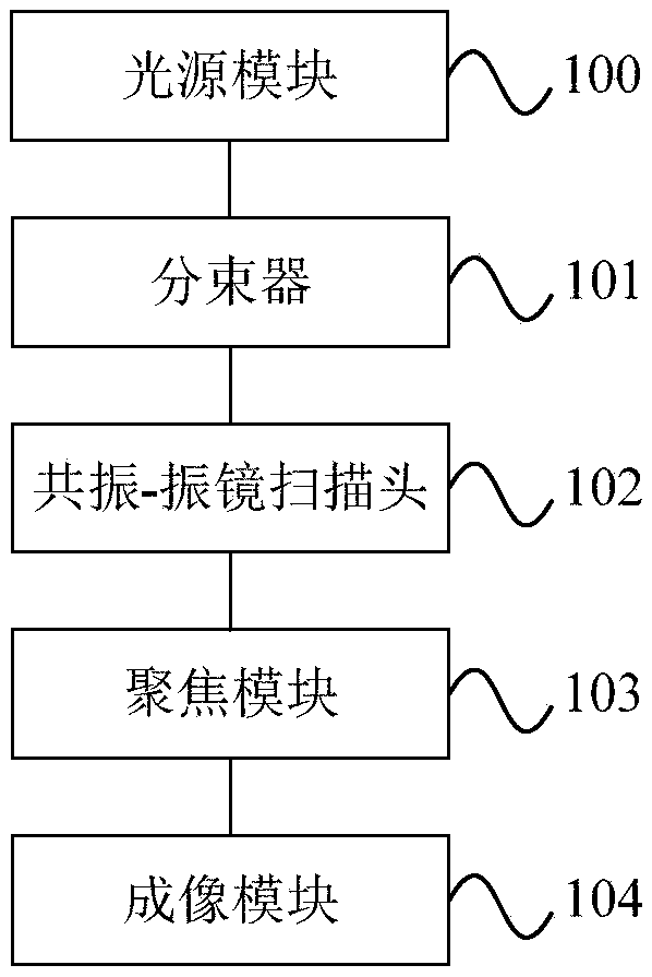
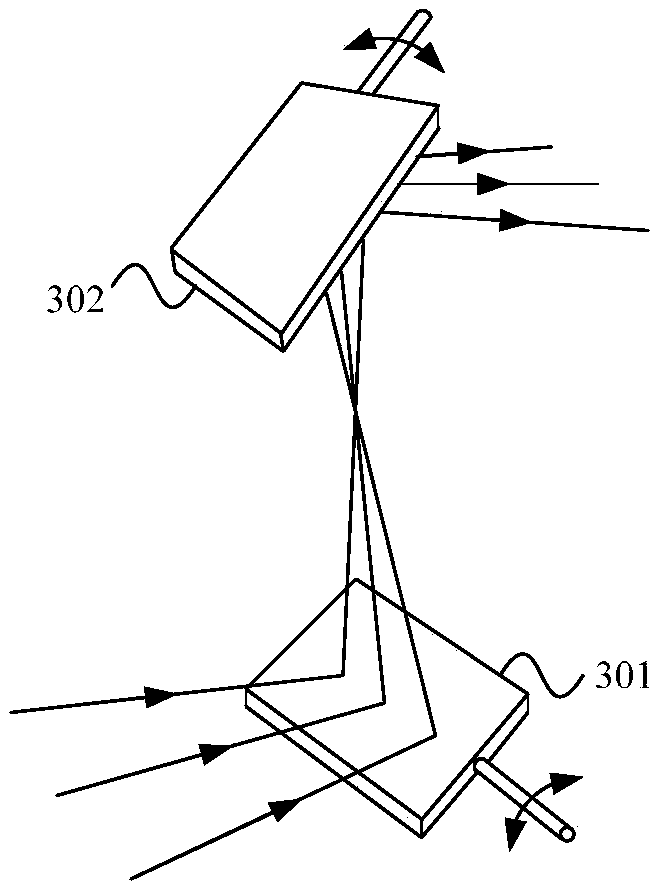
The invention provides a multi-beam multiphoton microscopic imaging device, comprising a light source module, a beam splitter, a resonance-galvanometer scanning head, a focus module and an imaging module. The light source module is used for generating a laser which can be used for multiphoton excitation. The beam splitter is used for generating a plurality of laser beams in a straight line of equiangular pitch. The scanning direction of the resonance scanning head and the galvanometer scanning head are perpendicular to each other, and the arrangement direction of the plurality of laser beams is consistent with the scanning direction of the galvanometer scanning head. The focus module is used for converting the laser emitted by the resonance-galvanometer scanning head into a focus spot of equiangular pitch and irradiating to the sample so as to excite a fluorescent or multiphoton high-order harmonic signal. The imaging module is for collecting fluorescent or multiphoton high-order harmonic signal for imaging. The multi-beam multiphoton microscopic imaging device provided by the invention adopts a plurality of laser beams located in a straight line, and the arrangement direction of the plurality of laser beams is consistent with the scanning direction of the galvanometer scanning head, thereby the plurality of laser beams scanning the sample simultaneously, which improves the imaging speed.

Description

technical field [0001] The present invention relates to the field of optical technology, more specifically, to a multi-beam multi-photon microscopic imaging device. Background technique [0002] With the development of science and technology, optical microscopic imaging technology has become an important technology and measurement method in biology, medicine and related interdisciplinary research. Due to the characteristics of non-invasive, non-invasive, and fast acquisition, optical microscopy imaging technology is very suitable for imaging of living cells, biological tissues and non-biological systems, and has advantages that cannot be replaced by other technologies. Therefore, in recent years, optical microscopic imaging technology has always been the frontier and hot spot of technological development, and has continuously achieved new developments and breakthroughs. Its development trend is higher spatial resolution, faster speed, and dynamic biological information acqui...

Claims


Application Information

Patent Timeline
IPC IPC(8): G01N21/64
CPCG01N21/6458
Inventor 唐云青张硕戴陆如
Owner 北京卓奥友科技有限公司
Learn More