A metal plate and strip roller quenching flow partition control device

A technology for metal strip and partition control, which is applied in the direction of quenching device, heat treatment process control, manufacturing tools, etc. The uniformity of water flow in the whole board and other issues can be achieved to improve drainage efficiency, not damage the surface quality, and achieve the effect of compact structure

Active Publication Date: 2019-08-09
NORTHEASTERN UNIV LIAONING
View PDF9 Cites 0 Cited by
  • Summary
  • Abstract
  • Description
  • Claims
  • Application Information

AI Technical Summary

Problems solved by technology

[0005] The existing spiral roller system in the high-pressure cooling section of the roller quenching machine has the following problems: 1) In order to realize the rapid discharge of the residual cooling water on the surface of the metal plate and strip to the edge, the spiral rollers spiral in opposite directions on both sides of the center line, and there is a hole in the center of the spiral roller. Processing tank, where the longitudinal water flow of the metal plate and strip is concentrated, which affects the uniformity of the water flow on the entire plate; 2) In order to improve the drainage efficiency of the water from the gap nozzle in the high-pressure cooling section of the roller quenching machine, the width of the spiral roll after the gap nozzle is 1 / 4 Drainage grooves are designed at the and 3 / 4 places, which affect the uniformity of flow in the width direction of the strips and cause problems in the shape of the strips after quenching
The above problems affect the uniformity of flow in the length, width and thickness direction of the metal sheet and strip roller quenching process, which in turn affects heat transfer and temperature drop, and ultimately affects the shape and performance uniformity of the sheet and strip quenching

Method used


Image

  • A metal plate and strip roller quenching flow partition control device
  • A metal plate and strip roller quenching flow partition control device

Examples


Embodiment 1

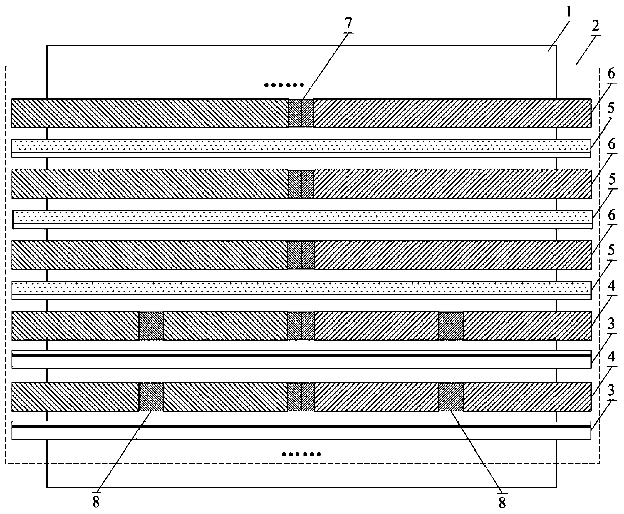
[0026] Embodiment 1 provides a specific implementation process of a metal plate and strip roll quenching flow zone control device of the present invention, such as figure 1shown. After the strip material 1 enters the high-pressure cooling section 2 of the roller quenching machine, it passes through the gap nozzle 3, the spiral roller 4 after the gap nozzle, the high-density nozzle 5 and the spiral roller 6 after the high-density nozzle in sequence. When the strip material 1 passes through the gap nozzle and the spiral roller 4, the jet cooling water in the middle of the gap nozzle 3 passes through the gap nozzle and the part of the water ring sleeve 7 in the spiral roller 4 is shunted to both sides in an orderly manner, which prevents the width of the strip material 1 from moving to the middle. The cooling water is deposited, and the cooling water is exported in an orderly and uniform manner to both sides. The cooling water near the 1 / 4 and 3 / 4 positions of the gap nozzle 3 pa...

Embodiment 2

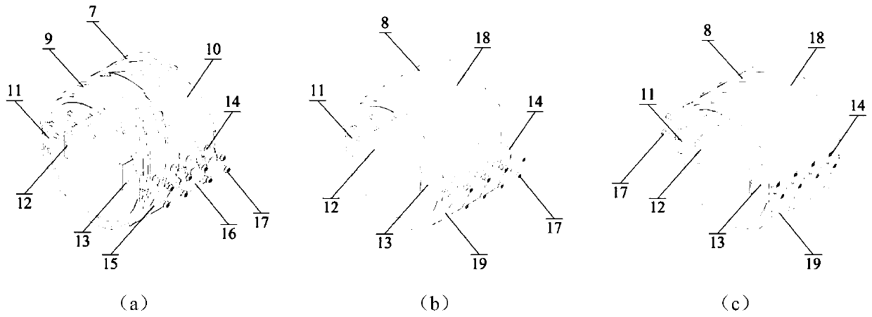
[0027] Embodiment 2 provides a specific installation process of a metal plate and strip roll quenching flow zone control device of the present invention, such as figure 1 , 2 shown. The middle part of the water ring sleeve 7 is installed in the middle processing groove of the helical roller 4 behind the gap nozzle of the high-pressure cooling section 2 of the roller quenching machine or the middle part of the helical roller 6 behind the high-density nozzle. The upper semicircular water diversion ring 10 is aligned and placed in the middle processing groove of the helical roller 4 behind the gap nozzle of the high-pressure cooling section 2 of the roller quenching machine or the middle part of the helical roller 6 behind the high-density nozzle. The connecting plate 12, the bolt fixing hole 13 on the connecting plate 12 corresponds to the bolt counterbore 14 on the outer surface of the upper left semicircular water diversion ring 9 and the upper right semicircular water divers...


PUM

PropertyMeasurementUnit
depthaaaaaaaaaa
widthaaaaaaaaaa

Abstract

The invention belongs to the technical field of heat treatment equipment for metal plates and strips, and discloses a roll-type quenching flow zone control device for metal plates and strips. The device includes the middle part water ring cover and the side part water ring cover; the middle part water ring cover is installed in the middle processing groove of the spiral roller behind the gap nozzle in the high-pressure cooling section of the roller quenching machine and the spiral roller behind the high-density nozzle; the side part water ring cover It is installed at the processing grooves at the 1 / 4 and 3 / 4 positions of the spiral roll width behind the gap nozzle in the high-pressure cooling section of the roll quenching machine. The device can effectively realize the uniform distribution of cooling water on the surface of the plate and strip, reduce the local uneven cooling caused by the deposition of cooling water, realize the orderly heat exchange on the surface of the plate and strip during the quenching process, and meet the high flatness of the metal plate and strip. High uniformity quenching production needs.

Description

technical field [0001] The invention belongs to the technical field of heat treatment equipment for metal plates and strips, and relates to a roll-type quenching flow zone control device for metal plates and strips. Background technique [0002] Metal sheet and strip heat treatment involves normalizing, quenching, tempering, controlled cooling, solid solution and other processes, among which quenching, controlled cooling, solid solution and other processes need to heat the metal sheet and strip to a certain temperature (generally ≥ 800 ℃) , using water cooling method to reduce the final cooling temperature of the process at a certain cooling rate, so as to achieve the purpose of improving the internal structure and structure of the metal and improving the performance. [0003] The heat treatment of metal plate and strip usually adopts roller hearth heat treatment furnace to complete the heating process, and adopts roller quenching machine to complete quenching, controlled co...

Claims


Application Information

Patent Timeline
Patent Type & Authority Patents(China)
IPC IPC(8): C21D1/667C21D9/46C21D9/52C21D11/00
CPCC21D1/667C21D9/46C21D9/52C21D11/00
Inventor 付天亮韩毅王昭东李勇田勇李家栋邓想涛王丙兴刘国怀
Owner NORTHEASTERN UNIV LIAONING
Why Eureka
Try Eureka