Use method of die cutting welding fusion equipment

A combination of equipment and die-cutting technology, applied in metal processing, etc., can solve problems such as high scrap rate and uneven folding force, and achieve the effect of improving folding quality, folding efficiency and quality, and ingenious design concept

Active Publication Date: 2019-01-15
青岛盈科精密橡塑有限公司 +1
View PDF3 Cites 0 Cited by
  • Summary
  • Abstract
  • Description
  • Claims
  • Application Information

AI Technical Summary

Problems solved by technology

[0006] S2. Connect the suction to the suction outlet of the mold, and set the suction parameters in the setting button, that is, adjust the wind speed according to the material of the heat connection; folding through the cooperation of the suction and the lower mold can effectively improve the efficiency of the folding action Uniformity and softness, and at the same time, the strength of folding can be controlled by adjusting the suction, so that the quality of folding is greatly improved, and at the same time, the problem of high scrap rate caused by uneven folding strength is effectively solved;

Method used


Image

  • Use method of die cutting welding fusion equipment
  • Use method of die cutting welding fusion equipment
  • Use method of die cutting welding fusion equipment

Examples


Embodiment 1

[0021] This embodiment involves a method of using die-cutting welding fusion equipment, which is realized through the following technical solutions:

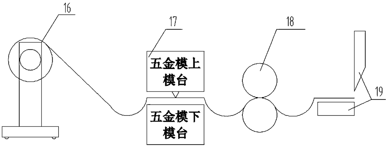
[0022] The method of using the die-cutting welding fusion equipment is divided into two parts. First, the PET film is stamped and cut by the flat punching forming equipment, and then the cut PET film is folded and thermally bonded by the high-frequency welding equipment; this embodiment When the high-frequency welding equipment involved is in use, the specific operation steps are as follows:

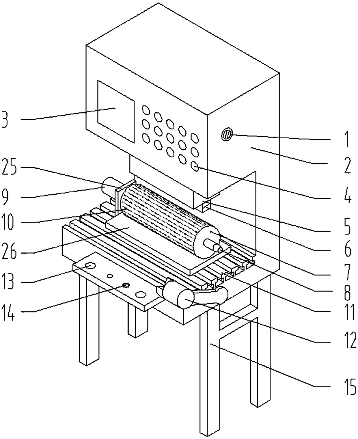
[0023] S1. Turn on the main power supply 1 of the machine, the display screen lights up, adjust the appropriate height of the upper mold 5 by setting the button 4, and install the lower mold 7;

[0024] S2. Connect the suction to the mold suction outlet 9, set the suction parameters in the setting button 4, that is, adjust the wind speed according to the material of the heat connection;

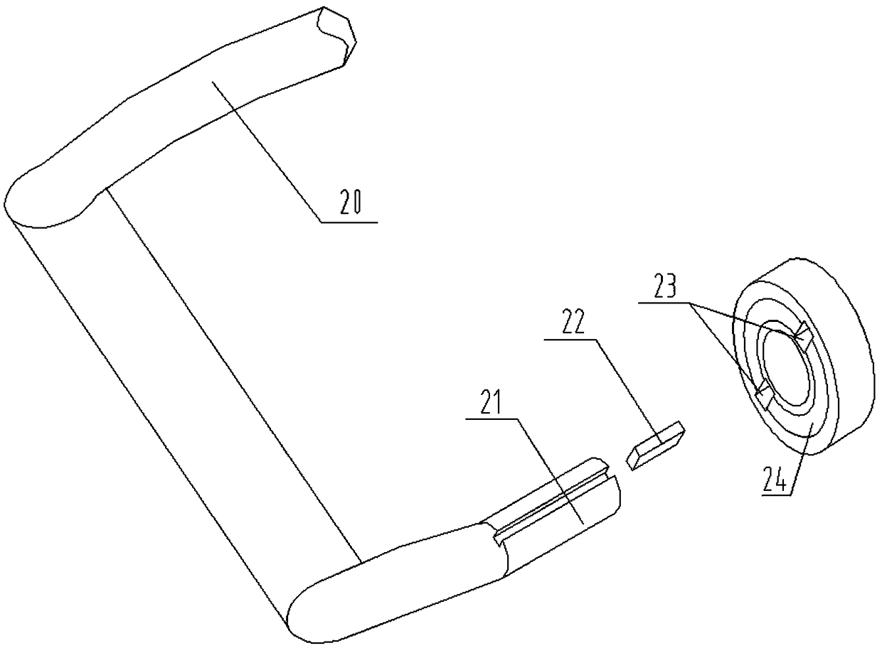
[0025] S3. Operate the rocker arm 20 to snap the s...


PUM


Abstract

The invention belongs to the research and development of a new process in the technical field of die cutting, and particularly relates to a use method of die cutting welding fusion equipment. The usemethod of the die cutting welding fusion equipment comprises the steps that firstly, a PET thin film is subjected to stamping forming and cutting through flat stamping forming equipment, and then thePET thin film which is cut into pieces is subjected to folding and rolling and hot welding through high-frequency welding equipment; when the high-frequency welding equipment is used, firstly the height of an upper die is adjusted, and a lower die is installed; then an induced draft assembly is connected to an induced draft outlet of a die, and induced draft parameters are set in setting keys; then a rocker arm is operated to clamp a locking block into locking holes for initial positioning, and then the induced draft assembly is opened by an operating key for folding and rolling; and finally,the upper die drives an upper die asbestos plate and heating sheet to move downwards by the operating key to enable the upper die asbestos plate and the heating sheet to move to the position where thefront and rear edges of the PET thin film to be hot welded coincide, and the upper die asbestos plate and heating sheet instantly generate heat to enable the PET thin film to be subjected to meltingand hot welding. The main structure is simple, and prepared products have the advantages of no deformation, no burrs, firm welding and uniform stress of stirring and rotation.

Description

Technical field: [0001] The invention belongs to the research and development of a new process in the field of die-cutting technology, and specifically relates to a method for using a die-cutting welding fusion device. Aiming at the new die-cutting process, ordinary flat punching products are welded with high frequency to form a ring-shaped closed product. Background technique: [0002] As we all know, the traditional die-cutting process basically adopts two schemes: flat punching and round knife roll-to-roll die-cutting, which are generally only suitable for flat two-dimensional products. The process has the advantages of low production cost, beautiful appearance, firm quality and strong practicability. However, with the continuous upgrading of electronic products, electronic die-cut parts are also changing with each passing day, and traditional techniques cannot meet the production needs of new products. In the face of industry competitiveness, it is necessary to meet cus...

Claims


Application Information

Patent Timeline
Patent Type & Authority Applications(China)
IPC IPC(8): B29C65/04B29C65/24B29C65/74B29C65/78B29C53/04B26F1/44
CPCB26F1/44B26F2001/4427B29C53/043B29C65/04B29C65/24B29C65/745B29C65/7802B29C65/7805B29C66/4312B29C66/863
Inventor 陈涛欧阳宝旭
Owner 青岛盈科精密橡塑有限公司
Why Eureka
Try Eureka