High-precision stress sensor based on Bragg fiber grating
A Bragg fiber and stress sensor technology, applied in the field of fiber optic sensors, can solve the problems of indeterminate frequency, unfavorable fiber optic sensors, and difficulty in filtering clean, etc., and achieves the effect of small phase detection error, wide application occasions, and reliable operation.
- Summary
- Abstract
- Description
- Claims
- Application Information
AI Technical Summary
Problems solved by technology
Method used
Image

Examples
Embodiment 1
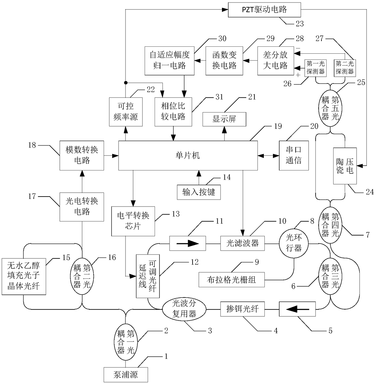
[0026] Embodiment 1 Overall structure of the present invention
[0027] like figure 1 Shown, the overall structure of the present invention has, pumping source 1 (the LC962U type pumping source of OCLARO company, central wavelength 980nm, the maximum single-mode output optical power is 750mW) and the first optical coupler 2 (OZ-OPTICS company produces The model is FUSED-12-1060-7 / 125-50 / 50-3U-3mm, the splitting ratio is 10:90 1×2 fiber optic coupler) connected to the input end, 90% output of the first optical coupler 2 The end is connected with the 980nm end of the optical wavelength division multiplexer 3 (COMCORE company 980 / 1060nm single-mode fiber wavelength division multiplexer), and the 1550nm end of the optical wavelength division multiplexer 3 is connected with the delay line adjustable optical fiber 12 (Sichuan Yuxingguang Technology Co., Ltd. Co., Ltd. VDL-40-15-S9-1-FA type motorized optical fiber delay line) is connected to one end, and the other end of the delay...
Embodiment 2
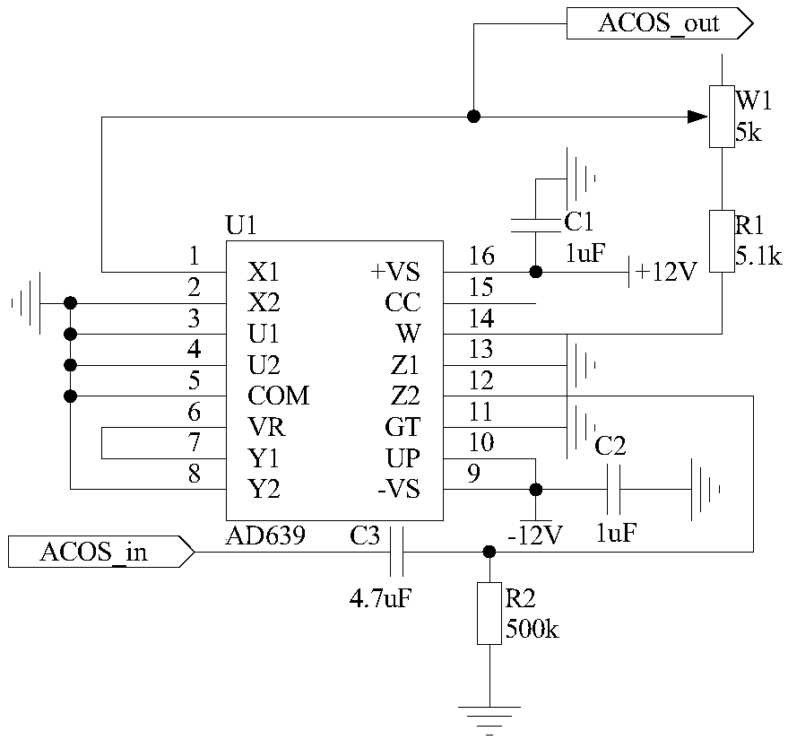
[0029] Embodiment 2 function conversion circuit
[0030] The structure of the function conversion circuit 29 is that one end of the capacitor C3 is connected to the pin 12 of the trigonometric function converter U1 and one end of the resistor R2, and the other end of the capacitor C3 is used as the input end of the function conversion circuit 29, which is recorded as the port ACOS_in , is connected with the output end of the differential amplifier circuit 28; the other end of the resistor R2 is grounded; the pins 2, 3, 4, 5, 8, 11, 13 of the trigonometric function converter U1 are grounded, and the pins 9, 10 are connected to the capacitor C2 One end is connected to -12V power supply, the other end of capacitor C2 is grounded; pin 6 of trigonometric function converter U1 is connected to pin 7, pin 16 is connected to +12V power supply and one end of capacitor C1, and the other end of capacitor C1 is grounded; The pin 1 of the trigonometric function converter U1 is connected to ...
Embodiment 3
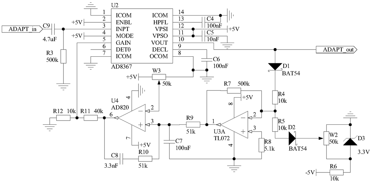
[0031] Embodiment 3 Adaptive Amplitude Normalization Circuit
[0032]Because the amplitude of the signal output by the function conversion circuit 29 is relatively small, and is affected by multiple parameters in the optical path and the circuit, the size is indefinite, so the present invention designs an adaptive amplitude normalization circuit 30, which is used to convert the signal output by the function conversion circuit 29 The amplitude is normalized to the optimal size to further improve the accuracy of demodulation. The structure of the adaptive amplitude normalization circuit 30 is that one end of the capacitor C9 is connected to one end of the resistor R3 and the pin 3 of the chip U2, the other end of the resistor R3 is grounded, and the other end of the capacitor C9 is used as an adaptive amplitude normalization The input end of the circuit 30 is recorded as the port ADAPT_in, and is connected with the port ACOS_out of the function conversion circuit 29; the pin 1, ...
PUM
| Property | Measurement | Unit |
|---|---|---|
| wavelength | aaaaa | aaaaa |
| reflectance | aaaaa | aaaaa |
Abstract
Description
Claims
Application Information
 - R&D
- Intellectual Property
- Life Sciences
- Materials
- Tech Scout
- Unparalleled Data Quality
- Higher Quality Content
- 60% Fewer Hallucinations
Browse by: Latest US Patents, China's latest patents, Technical Efficacy Thesaurus, Application Domain, Technology Topic, Popular Technical Reports.
© 2025 PatSnap. All rights reserved.Legal|Privacy policy|Modern Slavery Act Transparency Statement|Sitemap|About US| Contact US: help@patsnap.com