Construction method of post-pouring with side form for raft slab

A construction method and technology of post-pouring tape, applied in the field of construction, can solve problems such as inability to control construction quality, steel wire mesh cannot bear side pressure, etc.

Active Publication Date: 2021-01-19
CHINA MCC20 GRP CORP
View PDF5 Cites 0 Cited by
  • Summary
  • Abstract
  • Description
  • Claims
  • Application Information

AI Technical Summary

Problems solved by technology

When the area of ​​the basement raft is large, it is necessary to install a post-cast belt. The usual method is to hang a dense steel wire mesh at the joint of the post-cast belt, and fix a water-swelling water-stop strip in the middle of the steel mesh. When installing the concrete on both sides of the belt after pouring, or when installing the concrete after pouring the belt, the waterstop will swell with water and cannot protect it well; and when the concrete is vibrated, the steel wire mesh cannot bear the force of the concrete The side pressure and the rough surface cannot be formed, and the water stop strips often fall off or the steel wire mesh partially falls off, resulting in insufficient bite force between the post-cast concrete and the pre-cast concrete, and the stubble is not tight, so the construction quality is not easy to control, resulting in water seepage and other problems on the raft

Method used


Image

  • Construction method of post-pouring with side form for raft slab
  • Construction method of post-pouring with side form for raft slab

Examples


Embodiment Construction

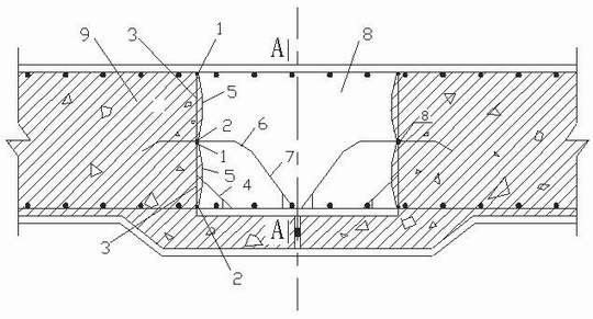
[0022] Example figure 1 with figure 2 Shown, the construction method of raft slab post-casting band sideform of the present invention comprises the steps:

[0023] Step 1, making upper chord steel bar 1, lower chord steel bar 2, belly bracing steel bar 3, side form brace 4, steel wire mesh 5, water-stop steel plate 6 and water-stop steel plate diagonal brace 7;

[0024] Step 2: Wrap the upper and lower sides of the wire mesh 5 around the upper chord steel bar 1 and the lower chord steel bar 2 for one turn, and then tie them firmly at intervals of 150mm;

[0025] Step 3. Place the water-stop steel plate 6 belly down symmetrically in the post-casting belt 8 and in the middle of the post-casting belt 8. Above the water-stop steel plate 6 is the upper side mold, and below is the lower side mold;

[0026] Step 4: The steel wire mesh 5 wound with the upper chord reinforcement 1 and the lower chord reinforcement 2 is respectively placed on the side wall of the post-casting belt 8 ...


PUM


Abstract

The invention discloses a construction method for a raft post-cast strip side form. Upper and lower sides of a steel wire gauze are separately wound with a ring of upper and lower chord reinforcing steel bars, and then are fastened firmly at intervals through binding wires; the web part of a water stop steel plate is downwards arranged in a post-cast strip; the portion over the water stop steel plate is an upper side form, and the portion under the water stop steel plate is a lower side form; the steel wire gauze is arranged on the side wall of the post-cast strip, and is separately positionedabove and below the water stop steel plate; the lower chord reinforcing steel bars of the upper side form and the upper chord reinforcing steel bars of the lower side form are alternated in a spacedmode along the centre line of the web part of the water stop steel plate, and are firmly welded with single surface of the water stop steel plate; web support reinforcing steel bars are arranged between the upper chord reinforcing steel bars and the lower chord reinforcing steel bars; side form inclined struts are in spot-welding connection with the web support reinforcing steel bars of the lowerside form; water stop steel plate inclined struts are in spot-welding connection with the water stop steel plate; and the upper chord reinforcing steel bars of the steel wire gauze and upper-layer ribcross joints of the raft are firmly tightened at intervals through bonding wires. The construction method can achieve the purposes of avoiding roughening, being good in waterproof effect, simple, convenient, economic and practical in construction, improves subsequent casting effect of post-cast strip concrete, and guarantees construction quality of the post-cast strip.

Description

technical field [0001] The invention relates to the field of construction, in particular to a construction method for post-casting belt side forms of raft slabs. Background technique [0002] The raft refers to the concrete slab in the foundation engineering, the foundation is under the slab, and there are columns, walls, etc. on the slab. Because it floats on the soil like a raft, it is called a raft, which is often used in the basement foundation of high-rise buildings. When the area of ​​the basement raft is large, it is necessary to install a post-cast belt. The usual method is to hang a dense steel wire mesh at the joint of the post-cast belt, and fix a water-swelling water-stop strip in the middle of the steel mesh. When installing the concrete on both sides of the belt after pouring, or when installing the concrete after pouring the belt, the waterstop will swell with water and cannot protect it well; and when the concrete is vibrated, the steel wire mesh cannot with...

Claims


Application Information

Patent Timeline
Patent Type & Authority Patents(China)
IPC IPC(8): E02D27/01E02D29/16
CPCE02D27/013E02D29/16
Inventor 陈智康星
Owner CHINA MCC20 GRP CORP
Why Eureka
Try Eureka