
Balancing control circuit of new energy electric vehicle

A technology for balanced control and electric vehicles, applied in electric vehicles, battery/fuel cell control devices, vehicle energy storage, etc., can solve problems such as large number of batteries, reduced service life of battery packs, and decreased mileage of electric vehicles. The effect of reducing the cost of use and prolonging the service life

Pending Publication Date: 2019-01-11
杨一威
View PDF0 Cites 0 Cited by
  • Summary
  • Abstract
  • Description
  • Claims
  • Application Information

AI Technical Summary

Problems solved by technology

[0002] At present, electric vehicle technology and hybrid electric vehicle technology are developing rapidly. The power source uses multiple battery modules connected in series to supply power for the vehicle. Therefore, there are a large number of batteries, so the monitoring of the state and performance of the batteries also more complicated
[0003] During the charging and discharging process of the battery, due to the change of the physical characteristics of the battery, such as the change of the activation voltage and the internal resistance of the battery, the consistency of each battery module is reduced, which will cause the performance of the battery pack to deteriorate or even be damaged, which greatly reduces the battery life. In the production of battery modules, due to the controllable difference range and the unequal voltage of each module, it brings many problems to the control of the battery system in the later period, and it is under unequal voltage conditions for a long time In this situation, the energy usage rate of the battery system in the later stage will drop sharply, and eventually the cruising range of the electric vehicle will drop sharply. In view of this situation, it is very necessary to develop a battery balancing system

Method used


Image

  • Balancing control circuit of new energy electric vehicle
  • Balancing control circuit of new energy electric vehicle
  • Balancing control circuit of new energy electric vehicle

Examples


Embodiment 1

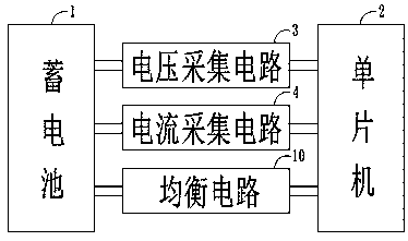
[0026] Such as figure 1 As shown, the new energy electric vehicle equalization control circuit includes: a battery 1, a single-chip microcomputer 2, a voltage acquisition circuit 3, a current acquisition circuit 4, and a temperature acquisition circuit 5. The output terminals of the battery 1 respectively pass through the input terminals of the voltage acquisition circuit 3. The input terminal of the current acquisition circuit 4 and the input terminal of the temperature acquisition circuit 5 are electrically connected to the single-chip microcomputer 2, and the model of the single-chip 2 is 89C51 series.

[0027] Such as figure 2 As shown, the voltage acquisition circuit 3 includes: diode D1, diode D2, voltage regulator W1, resistor R1, resistor R2, resistor R3, resistor R4, resistor R5, resistor R6, resistor R7, capacitor C1, capacitor C2, capacitor C3 and optocoupler Q1; one end of the resistor R7 is connected to the positive terminal and ground terminal of the voltage stabili...

Embodiment 2

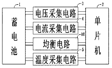
[0034] Such as image 3 As shown, the new energy electric vehicle equalization control circuit further includes a temperature collection circuit 5, and the output terminal of the battery 1 is electrically connected to the single-chip microcomputer 2 through the input terminal of the temperature collection circuit 5.

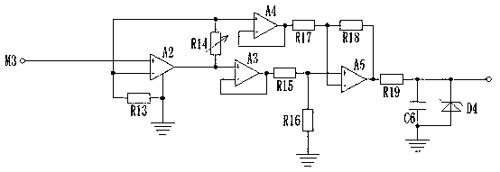
[0035] Such as Figure 4 As shown, the temperature acquisition circuit 5 includes: resistor R13, variable resistor R14, resistor R15, resistor R16, resistor R17, resistor R18, resistor R19, amplifier A2, amplifier A3, amplifier A4, amplifier A5, capacitor C6 and Zener diode D4; the models of the amplifier A2, amplifier A3, amplifier A4, and amplifier A5 are all LM358; the non-inverting input end of the amplifier A2 is connected to the terminal M3, and the inverting input end of the amplifier A2 is respectively connected to the variable resistor One end of the amplifier R14 is connected to the non-inverting input end of the amplifier A4, and the resistor R13 is connec...

Embodiment 3

[0038] Such as Figure 5 , Image 6 As shown, it also includes a wake-up circuit 6. The output terminal of the battery 1 is electrically connected to the single-chip microcomputer 2 through the input terminal of the wake-up circuit 6; the wake-up circuit 6 includes a clock chip U1 and a transistor Q2. The model of the clock chip U1 is SD2405, the wake-up circuit 6 includes the INT end of the clock chip U1 connected in series with the resistor R25 and then connected to the base of the transistor Q2. The connection between the resistor R25 and the base of the transistor Q2 is connected in series with the resistor R24 ​​and then respectively connected with the emitter of the transistor Q2 , 5V power terminal connected, the collector of the transistor Q2 is connected to the resistor R27 in series and then connected to the terminal M4, the terminal M4 is electrically connected to the output terminal of the battery 1, and the connection between the collector of the transistor Q2 and t...


PUM


Abstract

The invention discloses a balancing control circuit of a new energy electric vehicle, comprising a storage battery, a singlechip, a voltage acquisition circuit, a current acquisition circuit and a temperature acquisition circuit, wherein the output end of the battery is electrically connected with the singlechip through an input end of the voltage acquisition circuit, an input end of the current acquisition circuit and an input end of the temperature acquisition circuit respectively. The balancing control circuit of a new energy electric vehicle can detect the charging voltage and the chargingcurrent of the storage battery, sends the voltage signals and current signals collected by the voltage acquisition circuit and the current acquisition circuit to the singlechip for processing, and can preferably control the charging voltage value and the charging current value of each battery module when the battery module is charged, by means of the equalizing circuit, so as to enable each battery module to be placed in a balanced charging environment, thereby prolonging the service life of the battery modules and reducing the cost of use.

Description

Technical field [0001] The invention belongs to the technical field of battery management circuits, and specifically relates to a new energy electric vehicle balance control circuit. Background technique [0002] At present, electric vehicle technology and hybrid vehicle technology are developing rapidly. The power source uses multiple battery modules connected in series to supply power to the vehicle. As a result, there are a large number of batteries, so the status and performance of their batteries are monitored. It is also more complicated. [0003] In the process of charging and discharging the battery, due to the changes in the physical characteristics of the battery, such as the excitation voltage and the change in the internal resistance of the battery, the consistency of each battery module is reduced, which will cause the deterioration or even damage of the battery pack performance, which greatly reduces the battery pack The service life of the battery module is within t...

Claims


Application Information

Patent Timeline
IPC IPC(8): B60L58/18
CPCY02T10/70
Inventor 不公告发明人
Owner 杨一威
Learn More