
Center torsion bar type object mass center and rotational inertia measuring mechanism based on the knife edge support

A technology of knife-edge support and moment of inertia, applied in measuring devices, testing of machines/structural components, testing of static/dynamic balance, etc., can solve problems such as difficult operation at the center end of the rotating shaft, low efficiency, and low precision of the swing unit. Achieve the effect of saving time and labor

Pending Publication Date: 2019-01-08
ZHENGZHOU RES INST OF MECHANICAL ENG CO LTD
View PDF10 Cites 2 Cited by
  • Summary
  • Abstract
  • Description
  • Claims
  • Application Information

AI Technical Summary

Problems solved by technology

It is very troublesome in actual use. When converting between the measurement of the center of mass and the measurement of the moment of inertia, the lower end of the torsion bar must be fixed on the base of the shafting system, and the driving part of the shafting system at the lower end must be disengaged from the shafting system, so that the shafting system itself has no additional damping. , the locking of the center end of the rotating shaft is difficult to operate, and the efficiency is very low. The technology itself does not have the characteristics of integration with the centroid measurement
The tension spring type, compound pendulum type and leaf spring type arranged in the periphery are easy to realize the integration with the center of mass measurement, but the swing unit arranged in the periphery has significantly lower precision than the central torsion bar type

Method used


Image

  • Center torsion bar type object mass center and rotational inertia measuring mechanism based on the knife edge support
  • Center torsion bar type object mass center and rotational inertia measuring mechanism based on the knife edge support
  • Center torsion bar type object mass center and rotational inertia measuring mechanism based on the knife edge support

Examples


Embodiment Construction

[0031] The present invention will be described in detail below in conjunction with embodiment (accompanying drawing):

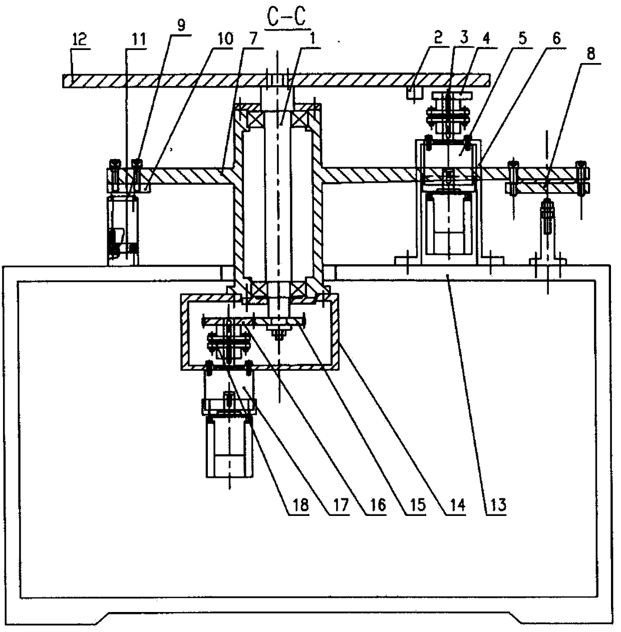
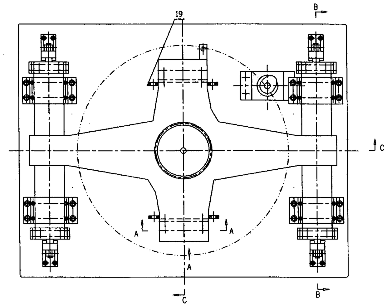
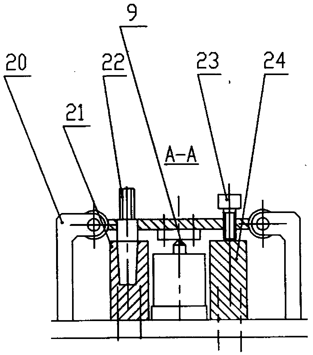
[0032] like figure 1 , 2As shown, the central torsion bar-type object center of mass and moment of inertia measurement mechanism based on the knife-edge support of the present invention includes a rotating shafting 1 that is vertically installed on the test bench through a shafting base 7 and has the function of a torsion bar. The rotating tray 12 on the top of the rotating shaft system; the front and rear lower blades 9 used to support the entire rotating system are coaxially arranged under the front and rear wings of the shafting frame 7, and are fixed on the test bench 13 through the connecting block 11 On the bottom surface of the front and rear wing plates of the shafting base 7 is fixedly connected with an upper plate 10 matched with the cutting edge of the lower knife edge, and the upper plate 10 is placed on the lower knife edge 9; on the left and ri...


PUM


Abstract

The invention discloses a center torsion bar type object mass center and rotational inertia measuring mechanism based on knife edge support. A problem is solved by a method of giving two functions through a center shaft, and the shaft is a reference shaft system for measuring the mass center rotation, and a swing torsion bar used for measuring the rotational inertia. According to the mechanism, atraditional design concept is broken through in the three aspects, firstly, the rigidity of the torsion bar should not be too large, otherwise an initial angle with a certain value is difficult to twist, and when the swing angle is large, the swing is stable, and the periodic measurement is facilitated; secondly, the rigidity is too large, the swing frequency is fast, and the swing period is difficult to measure; and thirdly, the rigidity of a rotating shaft for measuring the mass center should be large, a corner of the shaft system cannot be caused by a driving friction moment, and otherwisethe rotating shaft cannot stop immediately when the rotation is stopped and can swing in a reciprocating mode.

Description

technical field [0001] The invention relates to a high-efficiency measuring mechanism for center of mass and moment of inertia of a center torsion bar type object based on knife-edge support. Background technique [0002] The measurement of the mass, center of mass, and moment of inertia of an object is mostly used on space vehicles, such as the measurement of mass characteristic parameters of various warheads, satellites, spacecraft, and space stations. Accurate measurement of these parameters is essential for improving product flight stability and hit rate Less. The high-precision integrated joint measurement of the position of the center of mass and the moment of inertia is an unsolved problem. [0003] China has made great progress in this field in recent years, and there are several patented technologies. [0004] At present, most of the centroids are measured using three (or more) load cells to directly weigh and calculate or use the balance knife-edge principle. Th...

Claims


Application Information

Patent Timeline
Patent Type & Authority Applications(China)
IPC IPC(8): G01M1/10G01M1/12
CPCG01M1/10G01M1/122
Inventor 卢志辉张磊乐武艺泳孙志扬游广飞杨洪涛刘珉
Owner ZHENGZHOU RES INST OF MECHANICAL ENG CO LTD
Learn More