Eureka AIR delivers breakthrough ideas for toughest innovation challenges, trusted by R&D personnel around the world.

Blast furnace gas dust removing and discharging device

An ash unloading device and bag dust removal technology, applied in the direction of dust collectors, etc., can solve the problems of blockage of conveying pipelines, polluting the working environment, and affecting the stable operation of pneumatic conveying.

Inactive Publication Date: 2019-01-08
SICHUAN DESHENG GRP VANADIUM & TITANIUM CO LTD
View PDF3 Cites 0 Cited by
  • Summary
  • Abstract
  • Description
  • Claims
  • Application Information

AI Technical Summary

Problems solved by technology

[0003] At present, in the process of pneumatic conveying through the pipeline, there is a blockage in the pipeline, and the blocked pipeline needs to be partially removed for dredging. During this period, a large amount of bag ash falls to the ground, which seriously pollutes the working environment on site and increases the labor intensity of the post personnel. Problems affecting the stable operation of pneumatic conveying

Method used


Image

  • Blast furnace gas dust removing and discharging device

Examples


Embodiment 1

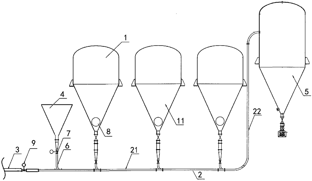
[0022] Such as figure 1 As shown, the present invention provides a blast furnace gas dust removal and ash unloading device, including: a bag dust removal box 1, an ash conveying pipe 2, a gas source pipe 3 and a funnel 4 connected to the ash conveying pipe 2, the ash conveying pipe 2 Including: an ash conveying main pipe 21 and an ash conveying branch pipe 22. One end of the ash conveying main pipe 21 is connected to the bag dust removal box 1 and the other end is connected to one end of the ash conveying branch pipe 22; the other end of the ash conveying branch pipe 22 is connected to the ash warehouse 5; The ash conveying main pipe 21 is connected to the lower end of the funnel 4 through a sandblasting cleaning pipe 6, and an electric ball valve 7 is provided on the sandblasting cleaning pipe 6.

Embodiment 2

[0024] Such as figure 1 As shown, the difference from Embodiment 1 is only:

[0025] The hopper 3 can hold and transport sinter particles, and the sandblasting cleaning pipe 6 can transport sinter particles. The ash branch pipe 22 is a straight pipe. The lower dust air chamber 11 of the bag dust removal box 1 is connected to the main ash conveying road 21, and the lower dust air chamber 11 of the bag dust removal box 1 is provided with an ash discharge hole 8. The number of the bag dust removal box 1 is several, preferably three. The gas source pipeline 3 is connected to the ash conveying main pipe 21, and the connection between the sandblasting cleaning pipe 6 and the ash conveying main pipe 21 is provided at the connection point of the bag dust removal box 1 and the ash conveying main pipe 21 Between the connection point of the gas source pipeline 3 and the ash conveying main pipe 21.

[0026] The gas source pipeline 3 is a nitrogen purge pipe, and a nitrogen purge valve 9 is...


PUM


Abstract

The invention discloses a blast furnace gas dust removing and discharging device. The blast furnace gas dust removing and discharging device comprises bag dust removing boxes, a dust conveying pipeline, a gas source pipeline connected to the dust conveying pipeline, and a funnel, wherein the dust conveying pipeline comprises a dust conveying main pipe and a dust conveying branch pipe, one end of the dust conveying main pipe is connected to the bag dust removing boxes and the other end is connected to one end of the dust conveying branch pipe; the other end of the dust conveying branch pipe isconnected to a dust bin; and the dust conveying main pipe is connected to the lower end of the funnel through a sandblast unblocking pipe on which an electric ball valve is arranged. The dust removingand discharging device can reduce the blocking frequency of the conveying pipeline, facilitate the timely unblocking of the dust conveying pipeline, reduce the labor intensity of post personnel, andensure the stable operation of pneumatic conveying.

Description

Technical field [0001] The invention relates to the technical field of smelting, in particular to a blast furnace gas dust removal and ash unloading device. Background technique [0002] In the blast furnace smelting process, the produced blast furnace gas is an important secondary energy source. Blast furnace gas has high dust content. At present, there are two ash conveying methods for dust collectors: one is mechanical conveying, mainly using screw conveyors or buried scraper conveyors to convey the dust out of the dust removal system; the other is pneumatic conveying, which uses gas Do load, transport through pipelines. Compared with mechanical conveying, pneumatic conveying has the advantages of good sealing, environmental protection, small investment, fewer failures, and no secondary pollution and gas leakage in the ash conveying process. Pneumatic conveying is the current development trend. [0003] At present, in the process of pneumatic transportation through pipelines, ...

Claims


Application Information

Patent Timeline
Patent Type & Authority Applications(China)
IPC IPC(8): C21B7/22
CPCC21B7/22
Inventor 张成勇江青芳陈继科毛晓斌徐瑜
Owner SICHUAN DESHENG GRP VANADIUM & TITANIUM CO LTD
Why Eureka
Eureka Blog
Learn More