Two-dimensional magnetically driven scanning micromirror based on mems technology and its preparation method

A technology of scanning micromirror and technology, which is applied to the technology for producing decorative surface effects, metal material coating technology, microstructure devices composed of deformable elements, etc., can solve the difficulty of integrating micro-actuating devices, sensors and There are huge differences in the working principle and structural scheme of the driver, and there is no process standard for MEMS devices, etc.

Active Publication Date: 2020-07-07
NANJING UNIV OF SCI & TECH
View PDF11 Cites 0 Cited by
  • Summary
  • Abstract
  • Description
  • Claims
  • Application Information

AI Technical Summary

Problems solved by technology

[0003] Compared with integrated circuits, the integration of micro-executive devices is more difficult. Due to the huge differences in the working principles and structural solutions of different sensors and drivers, there is still no specific standard for the process flow of MEMS devices in the industry.

Method used


Image

  • Two-dimensional magnetically driven scanning micromirror based on mems technology and its preparation method
  • Two-dimensional magnetically driven scanning micromirror based on mems technology and its preparation method
  • Two-dimensional magnetically driven scanning micromirror based on mems technology and its preparation method

Examples


preparation example Construction

[0038] A kind of preparation method of the two-dimensional magnetic drive scanning micromirror based on MEMS technology of the present invention, comprises the following steps:

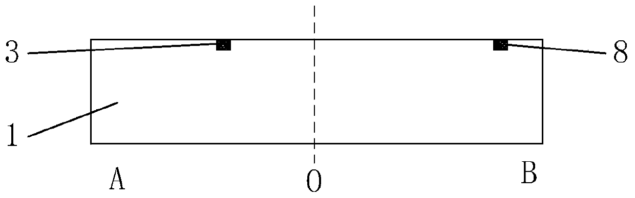
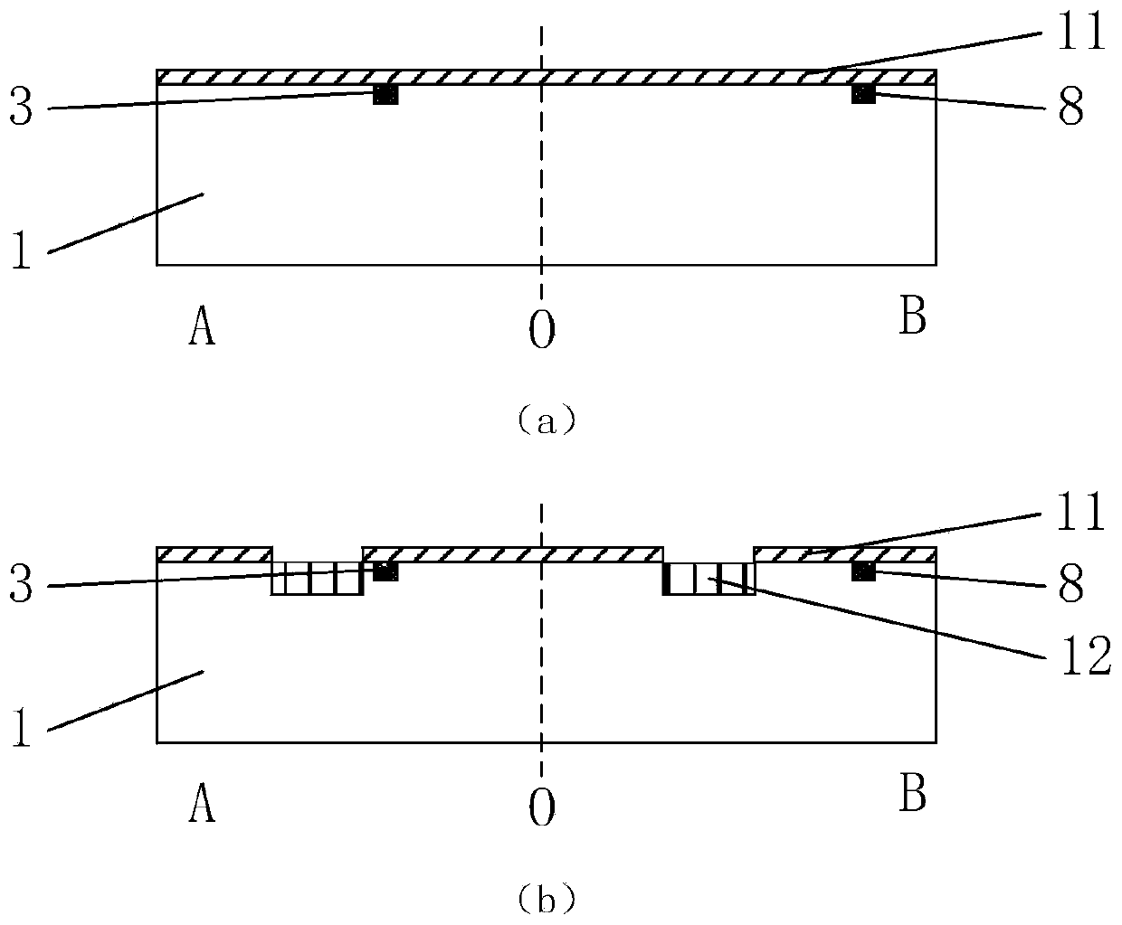
[0039] Step 1, preparing the first piezoresistive sensor 3 and the second piezoresistive sensor 8 on the silicon substrate 1;

[0040] 1.1. Photolithography forms the graphics of the first piezoresistive sensor 3 and the second piezoresistive sensor 8:

[0041] Coating positive photoresist on the silicon substrate 1, covering the mask plate provided with the patterns of the first piezoresistive sensor 3 and the second piezoresistive sensor 8, and performing exposure treatment to obtain the first piezoresistive sensor 3 and the second piezoresistive sensor The graph of resistance sensor 8.

[0042] 1.2. Perform reactive ion etching on the silicon substrate 1 to obtain the structures of the first piezoresistive sensor 3 and the second piezoresistive sensor 8, and obtain an alignment mark structure;

...

Embodiment

[0084] combine Figure 1 to Figure 7 , a two-dimensional magnetically driven scanning micromirror based on MEMS technology of the present invention, comprising a silicon substrate 1, a mirror substrate 6, a first piezoresistive sensor 3, a second piezoresistive sensor 8, a coil 9, a frame 10, an oxide insulating layer 4. Metal mirror layer 5, metal electrodes 14, coil leads 13, metal connecting wires, two first cantilever beams 2 and two second cantilever beams 7 arranged symmetrically to the center of the mirror base 6, and the two first cantilever beams 2 is perpendicular to the line connecting the two second cantilever beams 7;

[0085] The specific preparation process includes the following steps:

[0086] Step 1, preparing the first piezoresistive sensor 3 and the second piezoresistive sensor 8; as figure 2 shown;

[0087] 1.1. Photolithography forms the graphics of the first piezoresistive sensor 3 and the second piezoresistive sensor 8:

[0088] Coating AZ5214 posi...


PUM

PropertyMeasurementUnit
depthaaaaaaaaaa
thicknessaaaaaaaaaa

Abstract

The invention discloses a two-dimensional magnetically driven scanning micromirror based on MEMS technology and a preparation method thereof. The method comprises the steps of firstly, preparing a first piezoresistive sensor and a second piezoresistive sensor on a silicon substrate. Etching a coil groove and a coil lead groove on the silicon substrate; Preparing coils and coil leads; Forming an oxide insulation layer to build an insulation layer for interconnecting coil wires and metal connection wires; A metal electrode is prepare at that end of a coil lead wire, a metal mirror layer is prepare on a silicon substrate, and a metal connecting wire is prepared on an oxide insulating layer; Preparing a first cantilever beam, a second cantilever beam, a mirror substrate, and a frame; Fabricated micromirrors include deep channel loop coil, biaxial cantilever beam, mirror and frame, lead interconnect and lead insulation layer structure; Compared with the traditional technology, the scanningmicromirror based on the MEMS technology of the invention has the characteristics of small volume, high deflection frequency, large field angle and low cost, and has the possibility of embedded assembly.

Description

technical field [0001] The invention belongs to the technical field of microelectromechanical systems, in particular to a two-dimensional magnetically driven scanning micromirror based on MEMS technology and a preparation method thereof. Background technique [0002] With the advancement of micromachining technology and the application requirements of miniaturized sensor and actuator systems, the two-dimensional magnetically driven scanning micromirror based on MEMS technology is used as a micro-actuating device in LiDAR imaging systems. Its function is to obtain three-dimensional space information by changing the rotation angle of the mirror, changing the exit angle of the laser beam, receiving and processing after being reflected by the object. Compared with traditional mechanical radars, MEMS micromirrors generally require a surface size of more than 1mm, and the overall size is small, easy to drive, and has the possibility of embedded assembly. [0003] Compared with in...

Claims


Application Information

Patent Timeline
Patent Type & Authority Patents(China)
IPC IPC(8): B81B3/00B81C1/00
CPCB81B3/0018B81B3/0083B81C1/0015B81C1/00317
Inventor 姜波彭明迪苏岩朱欣华
Owner NANJING UNIV OF SCI & TECH
Why Eureka
Try Eureka