
Angle Changing Device Based on Off-Axis Parabolic Mirror for Large Aperture Parallel Beam

An off-axis parabolic mirror and parallel beam technology, which is applied in the optical field, can solve the problems of increasing the measurement system and data processing difficulty and complexity, difficulty in changing the angle of large-diameter parallel beams, and difficulty in manufacturing and installing mirrors. Good parallel quality, large diameter, simple and compact structure

Active Publication Date: 2018-03-02
XI AN JIAOTONG UNIV
View PDF5 Cites 0 Cited by
  • Summary
  • Abstract
  • Description
  • Claims
  • Application Information

AI Technical Summary

Problems solved by technology

Usually, the collimated and expanded laser beam consists of two sets of lenses and a spatial light filter. Limited by the existing lens processing technology and the influence of aberrations, the aperture of the lens is small and generally around tens of millimeters, which limits the The size of the beam aperture
Therefore, the area that can be measured each time is also small. For a large-area measured object, it often requires multiple measurements and then image stitching and other operations to obtain the final measurement result, which greatly increases the difficulty and complexity of the measurement system and data processing. degree; when deflecting the angle of a small-sized beam, a group of 4f lenses is usually added to the optical path, and the beam angle is deflected by a small movement of the lens, see Guo Xiaoming, Chen Chen, Wang Wensheng. Three-dimensional surface shape test based on digital holography[ J].Journal of Changchun University of Science and Technology: Natural Science Edition, 2015(1).; Or use the rotating table to control the mirror to deflect the angle, see Peng Z, Song Q, Li J.A sample test on the tilt angle of objectlight illumination in digital holographic 3D surface shape detection[J].ProcSPIE,2007:683212-683212-7; when the required beam aperture is large, the method of moving the lens itself limits the beam aperture, and the manufacturing and installation of large-area mirrors is extremely stable Resilience is also a problem, so neither beam deflection method is suitable
At present, in the measurement process, there are still great difficulties in changing the angle of the large-aperture parallel beam

Method used


Image

  • Angle Changing Device Based on Off-Axis Parabolic Mirror for Large Aperture Parallel Beam
  • Angle Changing Device Based on Off-Axis Parabolic Mirror for Large Aperture Parallel Beam

Examples


Embodiment Construction

[0017] The present invention will be further described in detail below in conjunction with specific embodiments, which are explanations of the present invention rather than limitations.

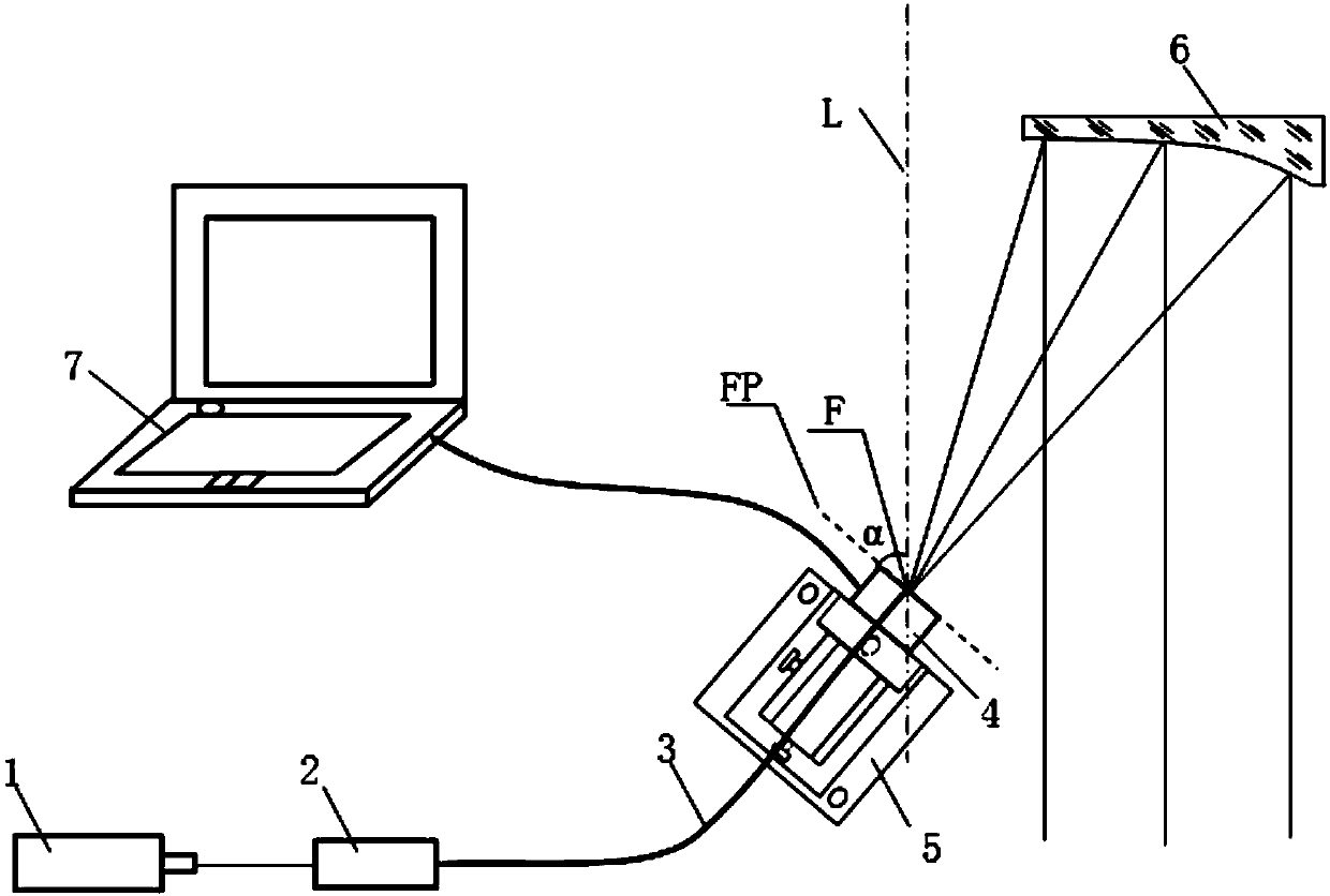
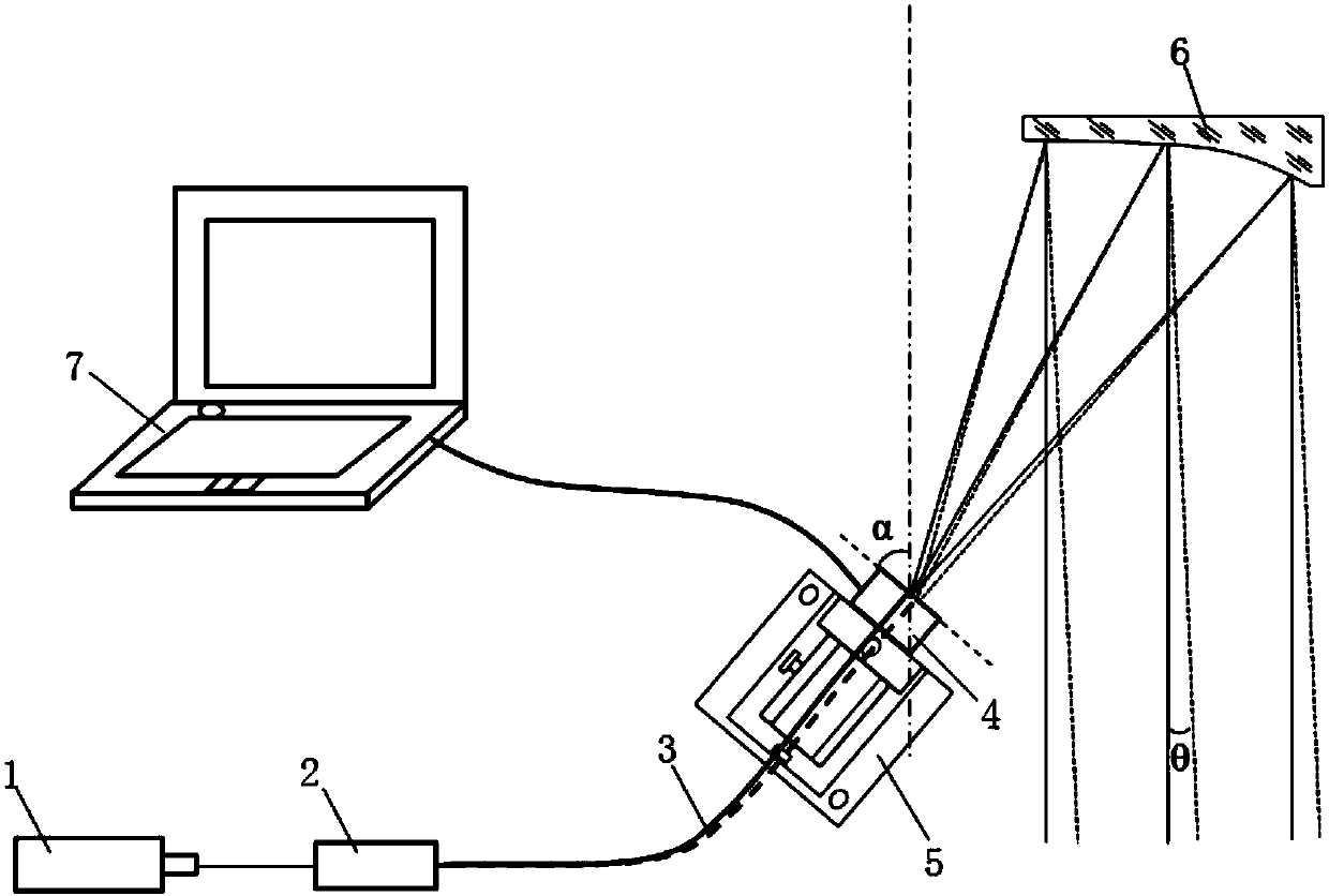
[0018] see figure 1 , the angle changing device based on off-axis parabolic mirror large-diameter parallel beams disclosed in the present invention, including laser 1, fiber coupler 2, single-mode optical fiber 3, precision linear displacement driver 4, five-dimensional adjustment frame 5, off-axis parabolic mirror 6 And control terminal 7 (can be terminals such as computer, panel computer, mobile communication equipment). The fiber coupler 2 has the ability to couple the laser beam of the laser 1 into a single-mode fiber 3 . The input end of the single-mode optical fiber 3 is fixed on the fiber coupler 2, the output end is fixed on the precision linear displacement driver 4 and is flush with the end face of the precision linear displacement driver 4; the precision linear displacement driver...


PUM


Abstract

The invention discloses an angle changing device for large-aperture parallel beams based on an off-axis parabolic mirror, and belongs to the technical field of optics. The angle changing device comprises a laser device, an optical fiber coupler, a single-mode optical fiber, a precise linear displacement driver, a five-dimensional adjusting frame, the off-axis parabolic mirror and a control terminal. The input end of the single-mode optical fiber is fixed on the optical fiber coupler, and the output end of the single-mode optical fiber is arranged in the end plane of the precise linear displacement driver and level with the end plane. The precise linear displacement driver is fixed on the five-dimensional adjusting frame and connected with the control terminal. The control terminal can control the precise linear displacement driver to drive the output end of the single-mode optical fiber to linearly move in the focal plane of the off-axis parabolic mirror. The device has the characteristics of being large in emergent beam aperture, great in beam parallel quality, simple and compact in structure and convenient to adjust and can further realize angular deflection of the large-aperture parallel beams to be adaptive to wide range measurement so that the complexity and the difficulty of wide range measurement can be reduced.

Description

technical field [0001] The invention belongs to the field of optical technology, and in particular relates to an angle changing device based on an off-axis parabolic mirror with a large-diameter parallel light beam. Background technique [0002] In optical applications, deflecting the collimated and expanded laser beam by a certain angle often occurs in the fields of optical interferometry and holography. Usually, the collimated and expanded laser beam consists of two sets of lenses and a spatial light filter. Limited by the existing lens processing technology and the influence of aberrations, the aperture of the lens is small and generally around tens of millimeters, which limits the The size of the beam aperture. Therefore, the area that can be measured each time is also small. For a large-area measured object, it often requires multiple measurements and then image stitching and other operations to obtain the final measurement result, which greatly increases the difficult...

Claims


Application Information

Patent Timeline
Patent Type & Authority Patents(China)
IPC IPC(8): G02B26/08
CPCG02B26/0816
Inventor 贾书海董君江超
Owner XI AN JIAOTONG UNIV
Learn More