Ultrasonic microbubble generation method, device and system

A generation device and ultrasonic technology, applied in the field of oil and gas exploration and development, can solve the problem that the gas production capacity has not reached the industrialized application and the like

Active Publication Date: 2019-01-08
PETROCHINA CO LTD
View PDF12 Cites 3 Cited by
  • Summary
  • Abstract
  • Description
  • Claims
  • Application Information

AI Technical Summary

Problems solved by technology

In order to obtain microbubbles with smaller diameters, the diameter of the generated bubbles can be controlled by further ultrasonic oscillation, which can reach a range of 1 to 50 microns, but this technology is still in the laboratory research and development stage, and its gas production capacity is far from reaching requirements for industrial applications

Method used


Image

  • Ultrasonic microbubble generation method, device and system
  • Ultrasonic microbubble generation method, device and system
  • Ultrasonic microbubble generation method, device and system

Examples


Embodiment Construction

[0042] In order to enable those skilled in the art to better understand the technical solutions in this specification, the technical solutions in one or more embodiments of this specification will be clearly and completely described below in conjunction with the drawings in one or more embodiments of this specification Obviously, the described embodiments are only some of the embodiments in the description, not all of them. Based on one or more embodiments in the description, all other embodiments obtained by persons of ordinary skill in the art without making creative efforts shall fall within the protection scope of the embodiments of the description.

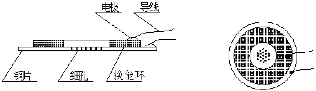
[0043] figure 1 Represents the vibrating plate of the existing method of generating bubbles, wherein, figure 1 The left figure is a side view of the vibrating plate, figure 1 The right figure in is a top view of the vibrating plate. Such as figure 1 As shown, the vibrating plate of the existing method of generating bubble...


PUM

PropertyMeasurementUnit
Thicknessaaaaaaaaaa

Abstract

An embodiment of the invention discloses an ultrasonic microbubble generation method, device and system. The device comprises a horn-shaped conductor, wherein the horn-shaped conductor comprises an upper horn-shaped body and a lower cylindrical body; the horn-shaped body is provided with a cavity with an opening in the upper part, a microporous vibration chip is fixedly connected with the upper end of the cavity, a micropore array of the microporous vibration chip corresponds to the opening in the upper part of the cavity, and a through hole allowing outside air to enter the cavity is formed in the upper side wall of the cavity; energy transition rings and electrode slices are arranged on the cylindrical body, the outer side of the cylindrical body is subjected to insulated enclosure, andconnecting wires of the electrode slices are led out through steel tubes and connected with an external ultrasonic oscillation controller. With the adoption of the device, the production quantity of the microbubbles can be substantially increased, and the device is safer and more efficient.

Description

technical field [0001] The invention relates to the technical field of oil and gas exploration and development, in particular to a method, device and system for generating ultrasonic microbubbles. Background technique [0002] Microbubble generation technology is gradually emerging in the field of greenhouse gas environmental protection and oil displacement technology development. In the field of petroleum development, the whole formed by dispersing micron-sized bubbles in the water phase is called the water-gas dispersion system. During oil displacement, tiny air bubbles can enter pores where injected water is difficult to enter, thereby improving sweep efficiency and improving recovery. Micron-sized bubbles are easy to expand in larger pores, which can block large pores and divert liquid to play a role in profile control. Oil flooding with water-gas dispersion system is an effective replacement method to continue to improve oil recovery in the later stage of water floodin...

Claims


Application Information

Patent Timeline
IPC IPC(8): B01F11/02B01F3/04B01J3/04B01J3/02
CPCB01J3/002B01J3/02B01J3/04B01F23/2373B01F23/238B01F31/89B01F31/85B01F2101/50B01F23/23123E21B43/20B06B1/0651B01D21/28B01D21/34E21B43/168
Inventor 陈兴隆俞宏伟李实韩海水姬泽敏
Owner PETROCHINA CO LTD
Why Eureka
Try Eureka