Supercharge Your Innovation With Domain-Expert AI Agents!

Guide rail block assembly and hot-bending forming device

A guide rail and guide block technology, which is applied in glass forming, glass reshaping, wood bending, etc., can solve problems such as instability, eccentric size, and inapplicability, and achieve the effect of ensuring stability

Pending Publication Date: 2019-01-04
LENS TECH CHANGSHA
View PDF0 Cites 1 Cited by
  • Summary
  • Abstract
  • Description
  • Claims
  • Application Information

AI Technical Summary

Problems solved by technology

[0003] At present, most of the 3D hot bending product forming machines adopt the integral forming method. This forming principle is only suitable for small-sized products and the bending depth is small. It is difficult to form products with a large bending depth and is not applicable, and it will easily cause eccentricity and size. Stability issue

Method used


Image

  • Guide rail block assembly and hot-bending forming device
  • Guide rail block assembly and hot-bending forming device
  • Guide rail block assembly and hot-bending forming device

Examples


Embodiment 1

[0040] The specific implementation of this embodiment is as follows:

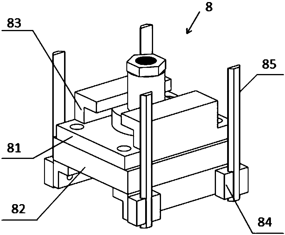
[0041] Such as figure 1 As shown, the rail guide block assembly 8 provided in this embodiment includes a first transition plate 81 and a second transition plate 82 from top to bottom, the first transition plate 81 is fixedly connected to the second transition plate 82, and the first transition plate The upper part of the plate 81 is fixedly provided with a cylinder connector, and on both sides of the second transition plate 82 are provided guide rails 85 and guide blocks 84 matching with the guide rails 85 .

[0042]It should be noted that, in the actual application process, the guide block 84 slides on the predetermined trajectory of the guide rail 85, which can transmit the kinetic energy of the forming cylinder and act on the forming press plate 9 of the upper mold, driving the forming press plate 9 of the upper mold to perform hot bending of the mold forming.

[0043] Preferably, the guide rail 85 is ...

Embodiment 2

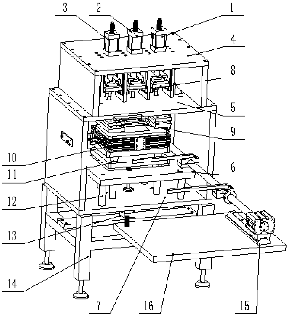
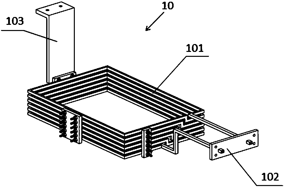
[0048] Such as figure 1 As shown in -5, the hot bending forming device for panel module assembly provided by this embodiment includes three forming cylinders arranged in sequence from top to bottom, the above-mentioned guide rail guide block assembly 8, upper mold forming pressure plate 9, heating copper Ring assembly 10, lower mold positioning plate 11 and the lower mold ejection cylinder 13 for lifting the lower mold positioning plate 11; each molding cylinder is connected with a guide rail guide block assembly 8 respectively, and the bottom of each guide rail guide block assembly 8 is respectively Connect the upper mold forming pressure plate 9; when forming, the inside of the heating copper ring is provided with a mold; each forming cylinder drives a guide rail guide block assembly 8 to perform hot-bending forming on the mold, and first use one of the forming cylinders to press the mold And pressurize the plane area of ​​the product, and then use the other two forming cyli...


PUM


Abstract

The invention provides a guide rail block assembly and a hot- bending forming device, and relates to the technical field of hot-bending forming. The device relates to the guide rail block assembly, afirst transition plate and a second transition plate are arranged from top to bottom in turn wherein the first transition plate is fixedly connected with the second transition plate; the upper part ofthe first transition plate is fixedly provided with a cylinder connecting piece; and the two sides of the second transition plate are provided with a guide rail and a guide block matched with the guide rail. The device also relates to a hot-bending forming device, which comprises three forming cylinders sequentially arranged from top and bottom, the guide rail block assembly, the upper die forming press plate, the heating copper ring component, the lower die positioning plate and the lower die ejecting cylinder used for lifting the lower die positioning plate; wherein each forming cylinder isrespectively connected with a guide rail block component. The hot-bending forming device is adopted to solve the problem that the existing hot-bending forming machine is only suitable for small sizeproducts and has small bending depth, and is not suitable for products with large bending depth.

Description

technical field [0001] The invention relates to the technical field of hot bending application, in particular to a guide rail guide block assembly and a hot bending forming device. Background technique [0002] Hot bending molding refers to the process of using a mold to press and shape the raw material when it is heated to a temperature around its melting point. Hot bending forming technology can be applied to materials such as glass, wood, plastic, etc. At present, hot bending forming molds are developing rapidly. [0003] At present, most of the 3D hot bending product forming machines adopt the integral forming method. This forming principle is only suitable for small-sized products with small bending depths. It is difficult to form products with large bending depths and is not applicable, and it will easily cause eccentricity and size. Stability issue. [0004] The information disclosed in this Background section is only intended to enhance the understanding of the gen...

Claims


Application Information

Patent Timeline
IPC IPC(8): B29C53/02B29C53/04B29C53/80B29C53/84C03B23/00C03B23/03B27H1/00
CPCC03B23/0066C03B23/03B27H1/00B29C53/02B29C53/04B29C53/80B29C53/84
Inventor 饶桥兵刘鑫平欧阳庚平
Owner LENS TECH CHANGSHA
Features
  • R&D
  • Intellectual Property
  • Life Sciences
  • Materials
  • Tech Scout
  • Unparalleled Data Quality
  • Higher Quality Content
  • 60% Fewer Hallucinations
Learn More