
Cold-accumulated oil-gas recovery processing device

A technology for oil and gas treatment and recycling, applied in gas treatment, steam condensation, membrane technology, etc., can solve problems such as shortening the switching time of heat exchangers, frequent start and stop of compressors, ice blockage of heat exchanger channels, etc., and achieve lower specifications , compression and stable operating conditions, and reduce maintenance costs

Pending Publication Date: 2019-01-01
北京恒泰洁能科技有限公司
View PDF0 Cites 7 Cited by
  • Summary
  • Abstract
  • Description
  • Claims
  • Application Information

AI Technical Summary

Problems solved by technology

When the oil and gas processing capacity is small, the energy consumption of the compressor is high, and it is easy to form overcooling, resulting in accelerated ice blockage of the heat exchanger channel and shortening the switching time of the heat exchanger; at the same time, the protection of the minimum cooling temperature will cause the compressor to start and stop frequently, accelerating Damage to wearing parts increases maintenance costs, so a cold storage type oil and gas recovery treatment device is needed to improve the above problems

Method used

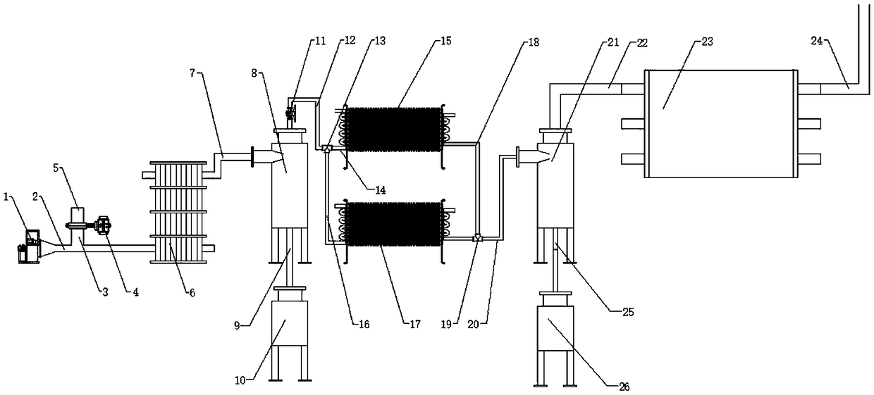
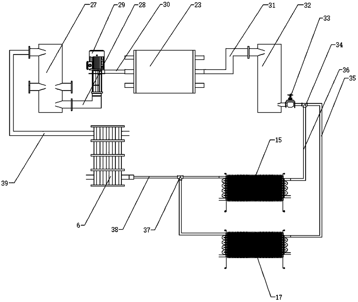
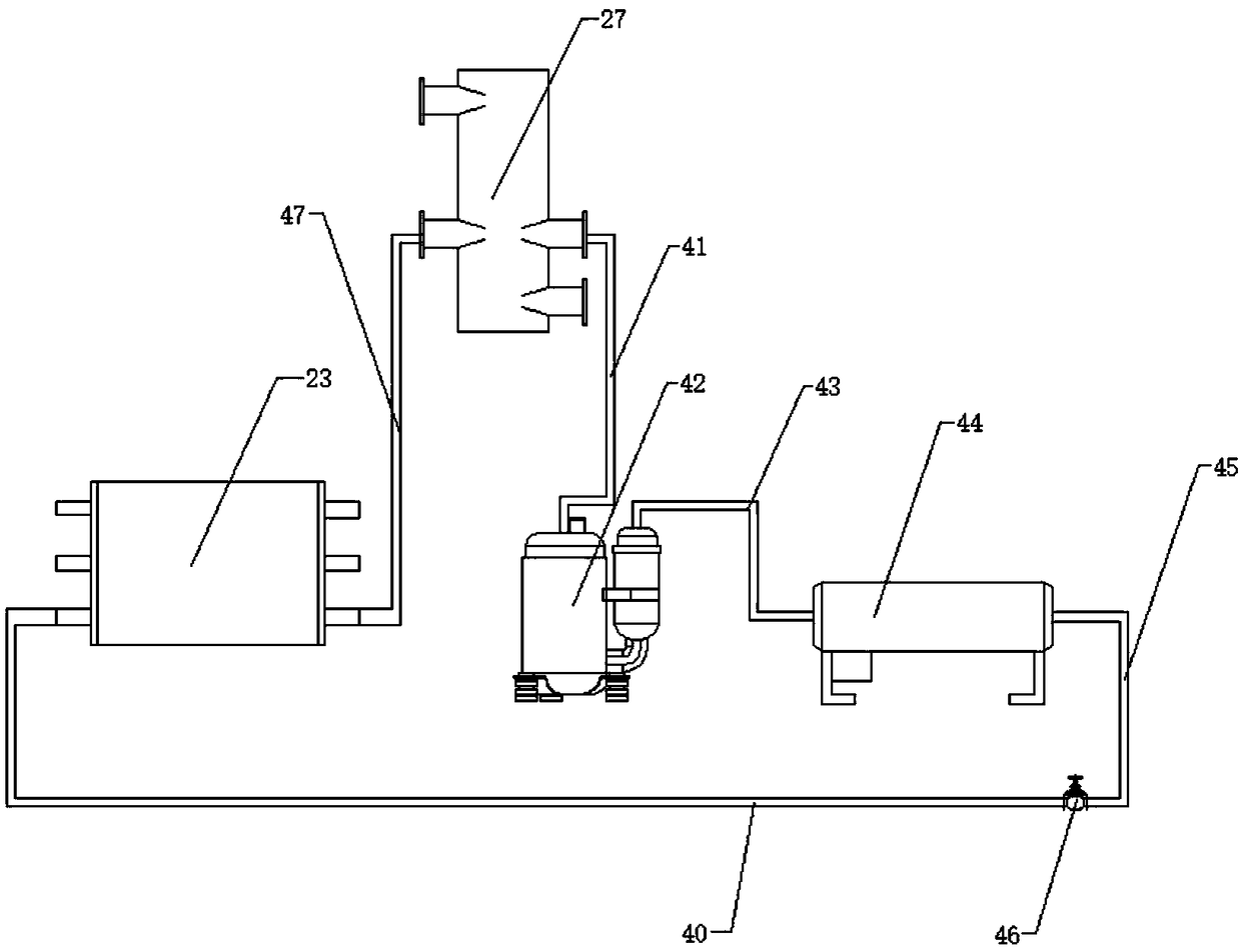

Image

  • Cold-accumulated oil-gas recovery processing device
  • Cold-accumulated oil-gas recovery processing device
  • Cold-accumulated oil-gas recovery processing device

Examples


Embodiment Construction

[0022] The technical solutions in the embodiments of the present invention will be clearly and completely described below in conjunction with the accompanying drawings in the embodiments of the present invention. Obviously, the described embodiments are only some of the embodiments of the present invention, not all of them. Based on The embodiments of the present invention and all other embodiments obtained by persons of ordinary skill in the art without making creative efforts belong to the protection scope of the present invention.

[0023] see Figure 1-4 , the present invention provides a technical solution:

[0024]A cold storage type oil gas recovery treatment device, comprising a booster fan 1 and a booster fan delivery pipeline 2, one end of the booster fan 1 is screwed to a booster fan delivery pipeline 2, and the outer wall of the booster fan delivery pipeline 2 is welded with an inlet The feed pipe 3, the end of the feed pipe 3 away from the booster fan conveying p...


PUM


Abstract

The invention relates to the technical field of the oil-gas recycling and in particular to a cold-accumulated oil-gas recovery processing device. The cold-accumulated oil-gas recovery processing device comprises an oil-gas processing unit, a secondary refrigerant unit and a refrigerating unit. The oil-gas processing unit is capable of, through a precooler, firstly separating a part of water, and cooling to a low temperature and freeze-separating the water through a coiled-tube-type heat exchanger, at the same time, condensing heavy components in an oil gas as liquid in the low temperature, andseparating and extracting in a gas-liquid separator. The secondary refrigerant unit is capable of, through a heat exchanger 6, absorbing cooling capacity of a low-temperature refrigerant and storingin a low-temperature storage tank, and through the coiled-tube-type heat exchanger 4a / b, performing heat exchange with the oil gas, and providing the needed cooling capacity for oil-gas separation. The secondary refrigerant unit is capable of, through regulating a flow of a secondary refrigerant returned from a low-temperature storage tank 9 to a normal-temperature storage tank 7, regulating oil-gas processing load. The refrigerating unit is capable of generating the cooling capacity. The cooling capacity is transmitted to an oil-gas separating unit through a secondary refrigerant system. A whole technological process is simple, and easy to operate. Cold is accumulated through the secondary refrigerant to adapt fluctuation of an oil-gas discharge quantity. The cold-accumulated oil-gas recovery processing device is capable of maintaining stable operation of the device, recovering usable components, eliminating potential safety hazards, and reducing economic loss, and has a certain promotion value.

Description

technical field [0001] The invention relates to the technical field of oil gas recovery and utilization, in particular to a cold storage type oil gas recovery treatment device. Background technique [0002] Oil and gas treatment and recovery are energy-saving and environmentally friendly high-tech. VOC recovery technology is used to recover VOC volatilized from oil products during storage, transportation, loading and unloading, so as to prevent air pollution caused by VOC volatilization, eliminate potential safety hazards, and improve energy utilization. , reduce economic losses, and thus obtain considerable benefits. In engineering, the method of "adsorption-condensation" is often used to recover oil and gas, so that it can meet the emission standard of non-methane total hydrocarbons ≤ 120mg / m3 stipulated in my country's "Petroleum Refining Industrial Pollutant Discharge Standard" GB31570-2015. [0003] However, the process of oil storage, transportation, loading and unloa...

Claims


Application Information

Patent Timeline
IPC IPC(8): B01D5/00B01D53/00
CPCB01D5/0036B01D5/0087B01D53/002B01D2257/708
Inventor 徐晓亮赵卿李腾张志杰
Owner 北京恒泰洁能科技有限公司
Learn More